
Steel roof and floor deck diaphragm design requires careful attention to load paths, stiffness variations, fastener types, and regional preferences…
Figure 1: In its most basic form, a diaphragm behaves as if it were a short, deep beam.
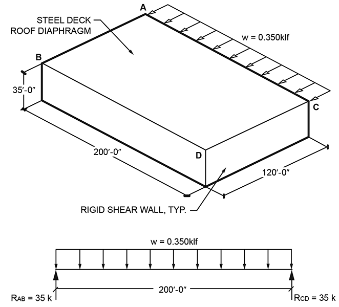
Shear diaphragms are commonly used in buildings as a means of transmitting lateral loads. In building design, these loads are typically caused by wind and seismic events, although earth and water can exert lateral forces as well. Steel deck, plywood, and concrete are all common materials utilized in diaphragm applications. In its most basic form, i.e. a rectangular, uninterrupted plane, a diaphragm behaves primarily as if it were a short, deep beam (Figure 1). Using this basic concept, the diaphragm shear forces can be determined and generally the same principles applied even with the introduction of roof openings or irregular building geometry.
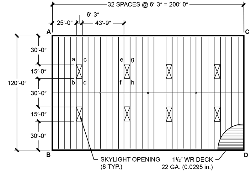
Figure 2: Skylight openings reduce diaphragm stiffness in the same manner beam web openings do.
Let’s start with the roof framing plan in Figure 2. We’ll use the same basic layout and service level wind pressure as shown in Figure 1, with the addition of (8) skylight openings in the roof. The openings reduce the diaphragm stiffness in the same manner that a beam web opening would reduce the beam stiffness at the location of the Figure 1 opening. We’ll need to ensure adequate fastening and transfer elements are provided to resist and transfer the design shear, including the distributed shear around the openings.
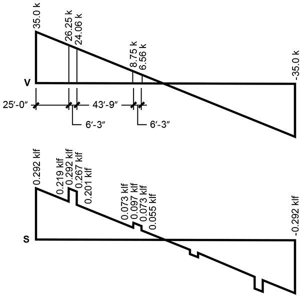
Figure 3: Shear around openings is determined based on forces and moments above and below each opening.
For this example, we are only going to consider wind in the direction shown, assuming half of the net pressure shown is windward on AC and half is leeward on BD. Constructing the shear diagram (V) in Figure 3, using the free-body diagram of Figure 1, shows us the maximum shear exists at the ends of the building, along AB and CD. The Figure 2 average shear (S) in the diaphragm is determined by dividing the shear by the length of the diaphragm at the location in question. The maximum average shear (Smax) in this example occurs both at the ends of the building, as well as in the deck panels and fasteners just to the right of the roof framing along AB (where average shear length is reduced due to openings), where Smax = 0.292 kips per linear foot (klf). Using the Steel Deck Institute (SDI) Diaphragm Design Manual, Third Edition, we can determine the required deck fastening. Using 5/8-inch puddle welds for attaching deck to supports and #10 sidelap screws, we find the nominal shear strength in the table for 0.0295-inch thick WR deck is 0.740 klf using a 36/4 (12-inch o.c.) support fastener pattern and (4) sidelap screws per span (15-inch o.c.). For ASD design, the wind factor of safety is 2.35, yielding an allowable shear force of 0.315 klf. This allowable shear force considers fastener strength and panel distortion around the fasteners; however, an additional check for stability must be made to ensure global buckling of the panel will not occur. The allowable buckling shear from the SDI table is 0.660 klf, so buckling will not occur.
Shear around Openings
The next step is to determine the shear around the openings. Since the building, opening locations, and loading are all symmetrical, we’ll look only at the (2) openings nearest the left end of the building (abcd and opening directly below). The (2) openings at the opposite end of the building will be the same, and the (4) openings near the interior will have different shear, but would be calculated using the same principles. From the average shear diagram (S) in Figure 3, we know the shear on the AB side of the openings is 0.219 klf and the opposite side is 0.201 klf. To determine the shear along the other (2) sides of each opening, we need to look at the rectangular deck areas directly above and below each opening. By constructing free-body diagrams of the areas in question, we can sum forces and moments around the area perimeters. Looking at the top 6-foot 3-inch wide x 30-foot long area, with base ac, we need to ensure the forces around the perimeter of that area are in equilibrium (Figure 4). We know from the S diagram in Figure 3 the left side shear force is 0.292 klf x 30 ft. = 8.76 kips (k) (upward) and right side shear force is 0.267 klf x 30 ft. = 8.01 k (downward). Summing moments about point (a) yields a shear force along the top (building perimeter above opening) of (8.01 k x 6.25 ft. + 0.175 klf x (6.25 ft.)2 / 2) / 30 ft. = 1.78 k (leftward). Then, summing forces in the horizontal direction yields an equal and opposite force of 1.78 k (rightward) along ac. This force must be transferred into the adjacent diaphragm areas (½ into each) immediately to the left and right of the opening. Since this force is in addition to the existing diaphragm shear in those areas, care must be taken to provide sufficient transfer length into those areas to prevent crippling of the deck at the associated corners of the opening. Using A653 SS grade 33 steel, the allowable strength of an arc spot weld can be determined by the equation 2.2tFu(d-t)/Ω = 2.2(0.0295 in.)(45 ksi)(0.625 in.–0.0295 in.)/(2.35) = 0.740k. The required number of fasteners to distribute the additional shear into adjacent diaphragms is (1.78 k)/(2 sides)/(0.740k/weld) = 1.2 welds per side, rounded up to 2. Since the diaphragm in the area in question is capable of resisting a maximum allowable shear of 0.315 klf, we should ensure that the transfer length provided into adjacent diaphragm areas is sufficient to limit the average total shear to 0.315 klf. To the left of the opening, the diaphragm is required to resist 0.219 klf due to applied loads, so the additional shear we’re introducing should not exceed 0.315 klf – 0.219 klf = 0.096 klf.
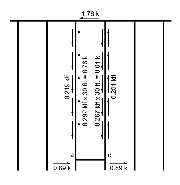
Figure 4: Forces around the perimeter of an opening must be brought into equilibrium.
The minimum transfer length or connection length can be determined by dividing the additional shear by the maximum additional shear calculated in previous step, (1.78 k)/(2 sides)/(0.096 klf) = 9.27 feet. Since this length exceeds the roof framing spacing, we’ll need to provide a transfer element, i.e. channel, angle, tube, etc., in line with ac that extends (2) spaces out to each side, upon which (2) 5/8-inch puddle welds should be placed approximately 4 feet 6 inches and 9 feet from a and c. Practically speaking in this example, since only (2) additional welds are required on each side, the deck could accommodate an additional weld at each of the (2) supports adjacent to a and c, in lieu of providing an additional transfer element. Moving on to the 6-foot 3-inch x 30-foot diaphragm area between the (2) leftmost openings, by inspection, the additional shears along bd will be similar to those calculated previously, since the area is the same size and shears are similar. The shear would be slightly less, since the applied load component is not present at the top or bottom of the area.
Transfer of Lateral Loads
Designing and specifying diaphragms to transfer lateral loads is a fairly involved process, becoming more complicated when openings and irregular geometry are introduced. There are many elements to be considered, including the interaction of the various structural components with varying stiffness. How the load travels from one part of the structure to another is highly dependent upon the stiffness of the components, the fasteners chosen, and the connection details in the areas where the forces are intended to transfer from one component to another. Careful consideration of the load path is critical in maintaining an economical, constructable diaphragm system. Drag struts and collector elements are often framed in the direction of the shear load, in order to progressively collect the load and distribute it into the structural framing system. In cases similar to the previous example, where the lateral load is being resisted by a horizontal diaphragm, a means of transferring the force from the diaphragm above to the structure below must be provided.
Suppose the roof framing at 6-foot 3-inch o.c. in the example (Figure 2) is an open web steel joist system, where the ends of the joists along walls AC and BD are bearing on a ledger angle on precast walls. When the wind is blowing on walls AB and CD, there must be a path for the shear in the diaphragm above the joists to transfer out into walls AC and AD. This may be accomplished in many ways; one of those would be via a deck bearing angle atop the joist ends adjacent to the wall, into the joist seats, into the ledger angle, and then into the wall; another being more direct via a deck bearing angle that is attached to the wall with sufficient fastening to directly transfer the shear from the bearing angle and into the wall; another would be to install channel members or HSS tubing to the ledger angle between the joist seats, such that the top of the tubing is at the same elevation as top of joists, and would provide deck edge support and a method for shear transfer into the ledger angle (eliminating the shear on the joist seats which have limited capacity for shear transfer), and into the wall.
Regional Preferences
So many choices – how do you choose? The answer lies in regional preferences, contractors and costs. Some erectors may prefer one method over another, and precast wall manufacturers will have preferences and associated costs as well. Steel joist seats have a fairly limited rollover shear capacity of around 2.5 kips service load at 2-1/2 inches deep. Thus, it is important whenever possible to provide an alternate means of shear transfer, such as the aforementioned channel or tube members, when shear loads begin to exceed the standard seat capacity. It is critical to provide adequate load paths, and for project teams to communicate with affected trades to determine the best option for the project. Similarly, deck fastening preferences vary regionally, and even vary among erectors within the same region. Diaphragm loads in the western U.S. are generally considerably larger than those present in the midwest. As such, a particular deck fastening and transfer system that typically works well in the western U.S. may be very uncommon, and/or unnecessary, in the midwest. Again, communication among the project team is important.
In summary, the next time you design a project with a diaphragm system, be sure to give careful consideration to ALL the details, from load paths, to stiffness variations, to fastener types, and regional preferences. The SDI Diaphragm Design Manual, Third Edition is an excellent design reference every engineer should utilize if designing with steel deck diaphragms. The manual includes pertinent design information, considerations, fastener information, deck shear capacity tables, and a plethora of highly relevant design examples, stepping you through all the intricate details and covering nearly any scenario you may run across.▪