
Design for Severe Earthquake and Deep Riverbed Scour
One of the greatest challenges to long-span bridge engineering is the forces of nature. Recent catastrophic events around the world reinforce the fact that nature can be destructive to infrastructure. At the Padma Bridge site in Bangladesh, AECOM used state-of-the-art technology and innovative disaster prevention and mitigation solutions to tackle some severe challenges.
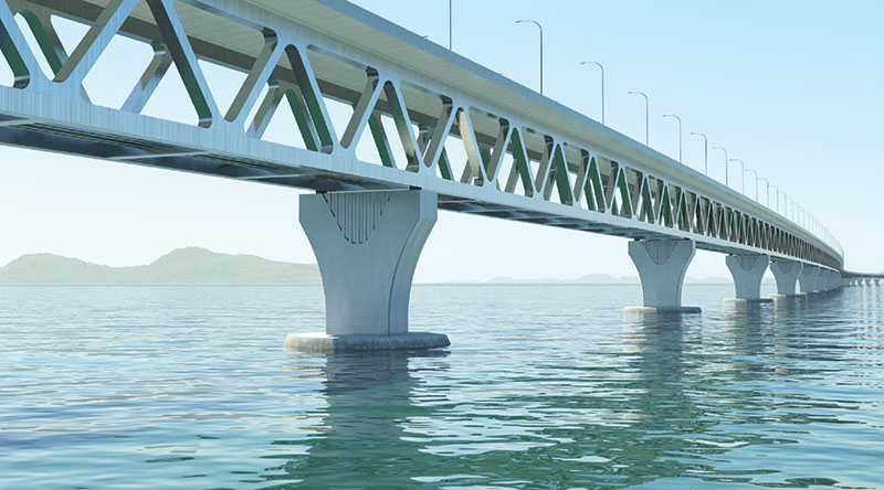
Padma Bridge – a 6.15km long, combined rail-road river crossing.
At 6.15 kilometers (3.8 miles) in length, the Padma Bridge is a landmark structure and one of the longest river crossings in the world. The Padma River is the third largest river in the world, and has the largest volume of sediment transport.
During monsoon seasons, the Padma River becomes fast flowing and is susceptible to deep scour, requiring deep-pile foundations for bridge stability. The Padma Bridge site is also in an area of considerable seismic activity, resulting in significant earthquake forces being exerted on the bridge. This combination, together with other forces of nature, posed a unique challenge.
The multipurpose Padma Bridge detailed design project has been successfully completed. AECOM developed alternative concrete deck forms, including an extradosed concrete truss bridge, a concrete girder bridge and a steel truss bridge. In all cases, a two-level structure was chosen, having significant advantages over a single level structure. These included segregated highway and railway envelopes to offer enhanced safety, improved operation, inspection, maintenance, and emergency evacuation procedures, as well as efficient provisions for utilities. With the railway in the lower deck, the structural depth beneath the railway is reduced, allowing the lengths of the railway approach viaducts for tie-in at the north and south banks to be minimized. With a two-level structure the construction cost is reduced, making the structure more efficient.
Analytical models were developed for each of the bridge forms to determine member sizes and, in particular, the weight of the superstructure. The steel truss bridge was found to be the most efficient with the lightest deck. Further details of this option were developed to determine the optimum span length. Total deck weight and foundation loads were compared for span lengths of 120 meters, 150 meters and 180 meters (394 feet, 492 feet and 591 feet, respectively). From this data, a construction cost was estimated for each span length with the optimum span being 150 meters. In conclusion, the most economic and appropriate form for the bridge was found to be the steel truss bridge with a concrete top slab acting compositely.
The multipurpose bridge also has many utilities built into it, including a gas pipeline, telecommunications and a high-voltage power transmission line. Additionally, it has emergency access points in order to facilitate evacuation of a train on the lower deck.
A detailed study of seismic hazard at the site was performed to determine suitable seismic parameters for use in the design. Two levels of seismic hazard were adopted: Operating Level Earthquake and Contingency Level Earthquake. Operating Level Earthquake has a return period of 100 years with a 65 percent probability of being exceeded during that period. Contingency Level Earthquake has a return period of 475 years with a 20 percent probability of being exceeded during a 100-year bridge life period. Any damage sustained from such an earthquake would be easily detectable and capable of repair without demolition or component replacement.
In conjunction with these investigations, AECOM carried out further analysis to determine the optimum foundation design, and two pile types were investigated; large diameter (3 meter; 10 feet) raking steel tubular piles and large diameter cast-in-situ concrete bored piles. Raking piles were more efficient in resisting lateral loads resulting from earthquake motions. This type of load is resisted as axial force in the steel piles, while the lateral load is resisted by the flexural capacity of the piles for the concrete bored piles. The very large bending moments generated by a seismic event dictated that insufficient flexural capacity could be created by reinforcement alone, and a permanent steel casing would be required to enhance the capacity down to 10 meters (33 feet) below the riverbed level, which for a 100-year scour event would be -61m PWD. It would also be necessary to have more than fifteen 3-meter (10 feet) diameter vertical concrete piles, compared to eight raking steel tubular piles. The large number of piles increased the weight of the pile cap and also the local scour. All of these factors had an adverse effect on the cost and constructability of the foundations, therefore the preferred solution was recommended as being the raking steel tubular piles.
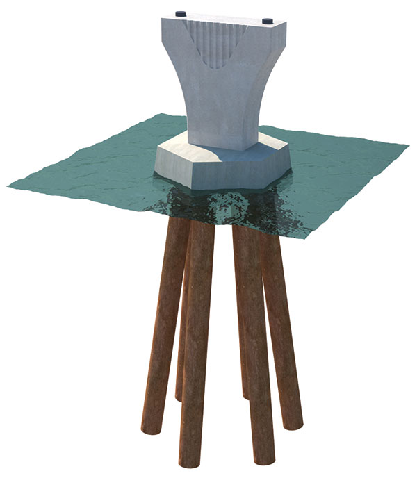
Raking steel tubular piles are very effective in withstanding large lateral forces. Some 60 meters (197 feet) of pile is unsupported due to
riverbed scour.
The behavior of the bridge is complex due to its height, which is 120 meters (394 feet) when the effects of scour are taken into consideration, and the large mass of the superstructure, pile caps and piles. A three-dimensional non-linear time history dynamic analysis, using a modified Penzien model, was adopted. It was divided into two parts, the structure and the free field soil. The interactions between the structure and the free field were simulated by lateral spring links. In order to determine the equivalent shear modulus and effective damping ratio between each layer of the soil, free field analysis was carried out beforehand using the Shake analysis program. Subsequently, a three-dimensional dynamic analysis was carried out using the equivalent shear modulus and effective damping as input data.
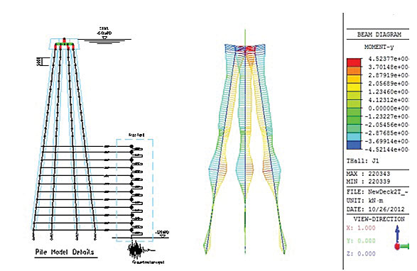
A structure-free field soil interaction model.
Ground motions were applied to the model to simulate the earthquake case, and loads were generated in the piles and substructure accordingly. Although other load combinations were considered, such as ship impact and wind, these effects were not found to be critical for the substructure, and the seismic load combination dictated the design.
A further model was developed to investigate the global behavior of the bridge. The bridge is divided into six span modules, each span 150 meters (492 feet) long, so the global analysis model examined an individual six span module and applied different levels of scour at each pier. A scour hole may form around an individual pier, or around two or more piers. The global model looked at various combinations in order to determine the critical axial, shear and bending loads on the foundations of any particular pier.
A three-dimensional global model for a 6-span bridge module.
Initial studies of the bridge were based on the deck being supported by traditional sliding bearings, with the point of fixity being the central pier of the six-span module. To avoid the fixed pier being heavily loaded during a seismic event by a longitudinal translation, shock transmission units were proposed at the free piers to ensure even load distribution between the piers. But under this system, the loads applied to the piers were still large; therefore, as part of the value engineering process, AECOM considered alternative forms of articulation.
The original seismic design strategy was to dissipate seismic energy through plastic hinges at the bottom of the piers. Further design optimization identified the benefits of seismic isolation, which allows the structure to behave elastically without damage. The application of seismic isolation has reduced the number of piles, the size of the pile caps and the size of the steel superstructure, resulting in a more cost effective design. Seismic isolation bearings have been used worldwide to mitigate seismic response by isolating structures from seismic input. They can accommodate thermal movements with minimum resistance, but will engage under seismic excitations. In this strategy, all primary structural members remain elastic without any damage or plastic hinging.
Principles of seismic isolation for Padma Bridge.
Isolation bearings contain three key elements: one to provide rigidity under service loads and lateral flexibility beyond service loads, one to provide self-centering capability, and one to provide energy dissipation. These key elements have to be properly designed and fine-tuned to achieve optimal seismic behavior.
Analyses indicate that seismic forces can be greatly reduced by replacing conventional pot bearings with isolation bearings. Friction pendulum bearings utilize the characteristics of a pendulum to lengthen the natural period of the isolated structure so as to reduce the input of earthquake forces. The damping effect due to the sliding mechanism also helps mitigate earthquake response. Since earthquake induced displacements occur primarily in the bearings, lateral loads and shaking movements transmitted to the structure are greatly reduced.
The reduced seismic loading generated at the top of the bridge piers significantly reduces pile loads. With the conventional scheme of bearings and shock-transmission units, eight raking steel piles were required for each pier; with seismic isolation this was reduced to six, leading to a savings in foundation costs of more than 20 percent.
AECOM then further developed the design with the inclusion of seismic isolation. The impact of the seismic isolation scheme is not limited to the substructure; the reduced seismic loading leads to reduction in section sizes for truss members, with an overall saving in truss steelwork of greater than 6 percent.▪