
Innovation at Federal Center South
Federal Center South Building 1202 is a state-of-the-art, high performance office space for the Seattle District Headquarters of the United States Army Corps of Engineers (USACE). KPFF Consulting Engineers provided both civil and structural engineering services, from the design competition phase through to completion of this showcase High Performance Green Building project. Top among the many innovative design features that the project boasts is perhaps the largest use of a composite concrete and timber floor system in the United States.
Composite concrete and wood floors were not part of the original design concept but ultimately became critical to achieving the project goals. This is that story.
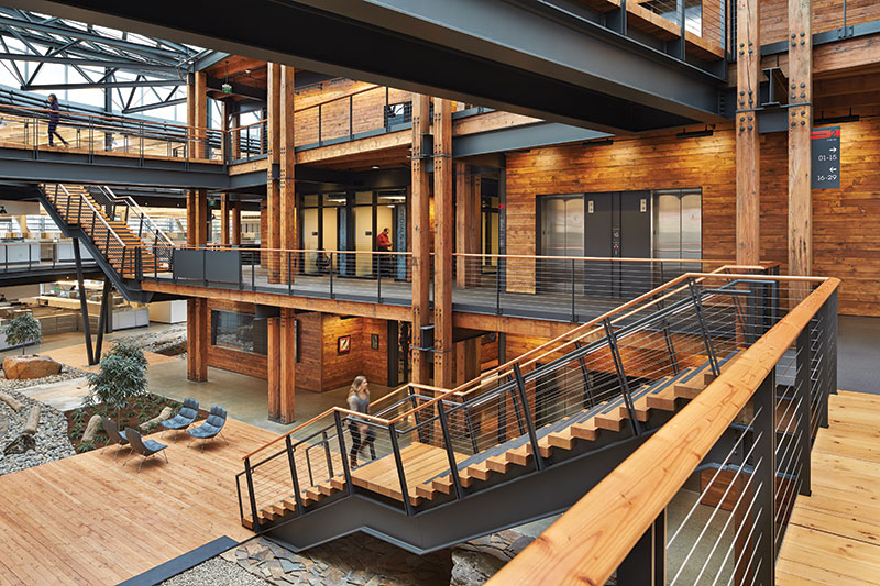
The Commons. Courtesy of Benjamin Benschneider.
Design-Build Competition
In 2009, the General Services Administration (GSA) solicited design-build proposals for a high performance office building for the USACE at the Federal Center South campus along the Duwamish Waterway in Seattle, Washington.
Led by Sellen Construction and ZGF Architects, LLP, the team won the design-build competition in March 2010. Integral to the winning design was the concept of reclaiming heavy timber framing from the existing 1940’s warehouse on the proposed building site, and incorporating it into a significant portion of the new facility.
The Commons
One of the more striking spaces in the building is the centrally located atrium, or the “Commons,” which includes a gathering place, conference rooms and shared facilities. The design called for a beautifully finished, exposed, concrete floor that could also be used to encapsulate and hide some building system elements such as conduit. A concrete floor also had the advantage of being highly durable and low maintenance, and could be used as a structural diaphragm to transmit lateral forces to concrete shear walls. There was also a strong desire that the structure of the Commons feature the salvaged timber. The final architectural/structural floor solution in the Commons consisted of 4 inches of concrete over salvaged 2×6 timber decking supported by 8×16 wood beams spanning an average of 22 feet.
This framing system was accepted by the GSA and was the basis for the pricing submitted by the design-build team.
Discovery after Deconstruction
After deconstruction of the existing warehouse, a comprehensive timber inventory was developed by the GR Plume Company, the timber fabricator. This led to the unfortunate discovery that not enough salvaged timber was recovered to completely frame the Commons if the beams were spaced at 4 feet on-center, the calculated spacing using the National Design Specification for Wood (NDS) for conventional non-composite timber beams.
A creative solution was required to save the design concept.
Test assembly diagram.
Defining a Solution
KPFF proposed completing the Commons using only the reclaimed timber from the old warehouse by increasing the beam spacing to 5 feet oc. and using composite construction. This innovative approach eliminated the need for non-salvaged timber and retained the character desired by the architect.
This was important because the intent was to expose all the framing and it would be difficult to match the aesthetic of the on-site salvaged timber with new wood pieces.
Although unproven, the team believed that using composite beams was a gamble worth taking, and one that seemed achievable within the schedule and budget. The GSA and USACE were approached about the idea, with the caveat that they would be able to review and approve both the design and testing procedures.
Approval was obtained to proceed.
Beam #3 test just prior to failure.
Design
While allowed by the current Uniform Building Code, a specific design methodology is not provided for composite concrete-timber beams by the National Design Specification® (NDS®), ACI 318, or 2009 International Building Code (IBC). This meant that testing would be required as an undefined system per IBC 1604.7. Interestingly, the Eurocode has a method for designing composite concrete-timber elements. In fact, several techniques for achieving composite action are used in Europe, often driven by a need to retrofit very old timber buildings.
KPFF’s approach for achieving composite action was to use lag screws as the connectors between the wood and the concrete. To control the number of lag screws required on each timber beam, lag screws were custom fabricated that contained a longer section of un-threaded bolt length than a standard lag.
This custom lag led to an innovative fabrication method by the GR Plume Company, which developed a drill bit that drilled two different hole diameters with a single plunge; a smaller one for the threaded portion and a larger one for the smooth shank. This streamlined the amount of labor required to drill all the lag screw holes and install the lags.
Now all that was needed was to put the assembly to the test.
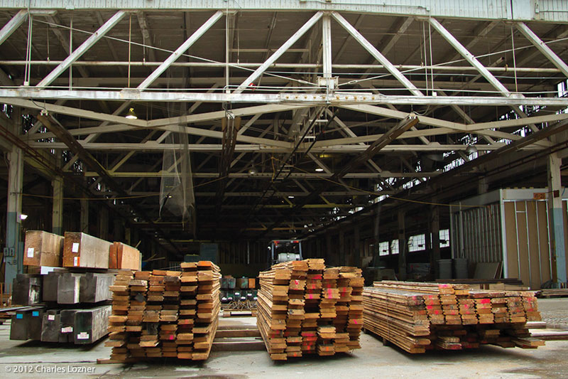
Deconstruction of the warehouse. Courtesy of Charles Lozner.
Test Procedure
The team initially chose 3 full-size, representative beams from the salvaged timber for full scale testing. It was acknowledged that 3 samples would not necessarily represent a significant statistical data set, and that the result of each test sample would ultimately have to be taken on its own merits. Then a decision would have to be made as to whether to proceed with construction using composite beams.
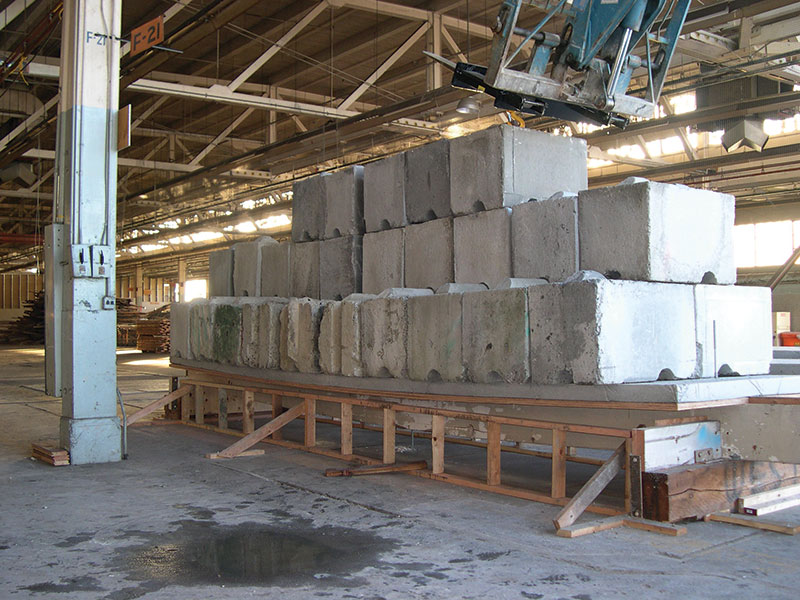
KPFF developed a test procedure in accordance with IBC section 1715. The procedure addressed the physical test setup, the load increments (concrete eco-blocks), the order and location of how the load increments would be applied, what kind of data would be collected, how the beams would be instrumented, and what the criteria for success and failure would be. It was also critical that all aspects of the test assemblies replicate the eventual in-place construction as close as reasonably possible.
The onsite testing was conducted in an area of the warehouse that had previously been used for heavy manufacturing. KPFF performed finite element modeling to evaluate the existing slab and foundations below where the testing would occur. The analysis demonstrated that the testing would not be affected by deflections of the existing floor and foundation system.
Another issue was how to pour the concrete slabs for each test beam. The actual building construction would involve single span wood decking spanning between the beams. In order to produce a flat surface for the bottom form of the concrete, but still ensure a direct connection between the slab and the beams, small notches were cut into the top of the beams to create seats for deck bearing. This kept the top of decking relatively flush with the top of the beams and allowed direct contact between the slab and the beams.
Since the test slabs would need to include only half of a span on each side of a beam, the edges of the concrete were supported by short “pony walls”. It was critical to repeatedly cut down these walls to shorten them after the initial concrete set to ensure they were not shoring up the composite slabs during the curing process. These walls remained as a safety measure during test loading.
Initial Beam Testing
Before installing the decking, lag screws, reinforcement, and slabs, it was decided to try and obtain modulus of elasticity (E) values for the bare beams. A test was performed to load a beam with a single load increment, measure the deflection and back-calculate a value of E. Additionally, vibration testing was performed to establish the natural frequency and back-calculate an E value using the vibration response.
This testing indicated an average E of 2,500 ksi, compared to the NDS design value of 1,600 ksi. Taking the time to establish this true value of E would prove to be a very useful decision.
After the composite test beams were constructed, the slabs were allowed to cure for 28 to 30 days, with 12 to 14 deflection measurements taken to evaluate creep over the cure time. The amount of measured creep for the 3 beams ranged from about 3/16 to ¼ inch, showing very little spread between them.
Sellen constructed the test beams, support frames, and loaded the beams during testing. KPFF instrumented the beams and took measurements during the tests. GSA and USACE were kept aware of the testing process and were invited to attend.
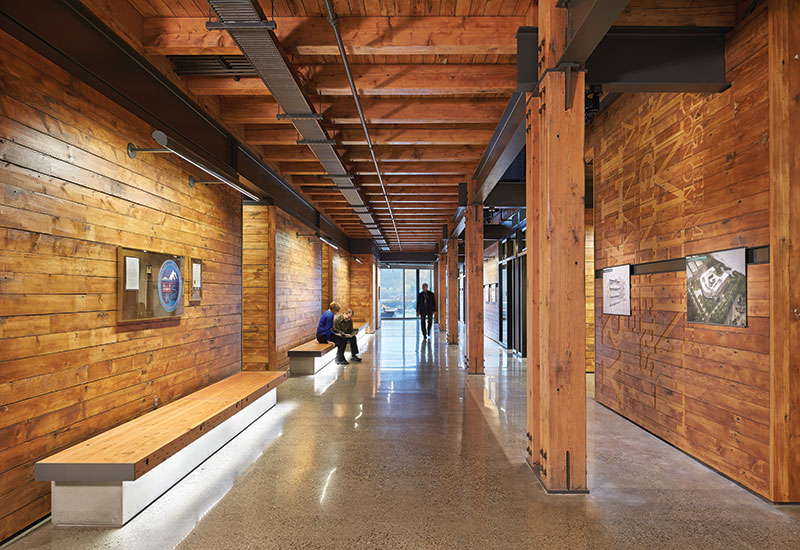
Commons interior. Composite floor above. Courtesy of Benjamin Benschneider.
Final Testing
With the test specimens cured and in place, it was time to try to break things!
The test process required that each composite beam hold twice the design live load (2×80 psf) for 24 hours and then be able to recover 75% of the measured deflection within 24 hours of being unloaded. The first beam passed this test with flying colors, as did the other two. In fact, one beam recovered 91% of its measured deflection from this portion of the test. None of the three exhibited any physical signs of distress from this initial loading phase.
After conducting the required test for twice the live load on each specimen, each beam was tested with the intent of failing it. For beam #1, concrete eco-blocks (weighing 1750 pounds each) were placed until the beam was carrying 38,500 pounds of blocks, or more than 400% of the design live load. This was unexpected. Additionally, there were no visible signs of distress at that point. It was decided to stop at that load and let it sit fully loaded for 24 hours. No visible signs of distress were observed after 24 hours.
For beam #2, concrete blocks were stacked on the assembly until 56,000 pounds of load was present, more than 600% of the design live load. At this point there were safety concerns because the entire slab-beam “T” section was beginning to rotate; loading was stopped in order to avoid the whole assembly toppling over. No visible signs of failure or distress were observed then, or after the blocks were removed. The deflection gages had maxed out with a value of 1.285 inches at around 550% of design live load.
Due to the experiences with beams #1 and #2, the loading procedure for beam #3 was altered to use larger eco-blocks for the initial loading course to allow more weight to be stacked with a lower center of gravity. At just over 500% of the design live load, a small crack was detected around a knot at about a third point in the beam span. At about 650% of design live load, the crack lengthened and a series of cracking sounds were heard. Finally, at 61,250 pounds of load, it was decided that it wasn’t safe to load the beam any further. About 10 minutes after this last load increment was placed, the wood beam failed in flexure with a sudden, loud crack!
Composite Action
All three of the test specimens supported significantly more than the required load with no signs of distress. There was no question that the system had adequate capacity, but how much composite action was achieved?
After analyzing the deflection results, it was estimated that the amount of composite action achieved probably ranges from 60% to 80%, depending the value of “E” used in the calculation. It is likely closer to the lower end of this range, which is consistent with results from testing in Europe for systems with lag screws. If higher composite action is required, then a different technique should be used to develop the composite action. In our case, it was enough.
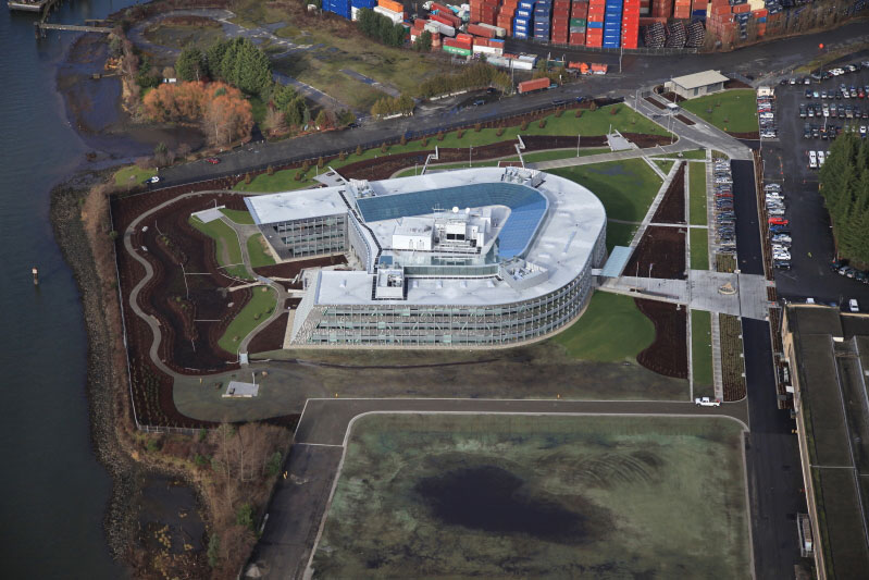
Aerial of completed project.
Summary
Federal Center South Building 1202 is a definitive statement that visionary architecture, innovative engineering and design/build delivery methods can produce world class architecture worthy of celebration. Creative problem solving, a willingness to take risks, and a high degree of trust within the design build team all combined to allow the delivery of a world class facility with a truly innovative concrete and timber composite floor system.▪
Building Data:
Size: Three-story, 209,000 SF building
Reclaimed heavy timber and decking in Commons: 300,000 BF
Targeting LEED Gold
Team:
Owner: General Services Administration (GSA)
Tenant: United States Army Corps of Engineers (USACE) Seattle District
Structural & Civil Engineer: KPFF Consulting Engineers
Contractor: Sellen Construction
Timber Fabricator: GR Plume
Architect: ZGF Architects, LLP
Funding: American Recovery and Reinvestment Act (ARRA)