
Part 2: Test Protocols and Case Studies
As discussed in Load Testing of Concrete Structures – Part 1 (STRUCTURE® magazine, April 2014), load testing can be used to determine the ability of a structure to carry additional loads, to establish the safety of structures, to validate strengthening, to gain knowledge on the behavior of a structure, and to supplement, validate or refine analytical work models. Part 1 discussed different aspects of in-situ load testing including the load test program, methods of load application and instrumentation. Part 2 describes the load test protocols and presents case studies to illustrate the use of in-situ load testing in the evaluation of existing concrete structures.
Load Test Protocols
In the United States, there are two protocols for load testing of concrete structures: Monotonic and Cyclic. These load test protocols are standardized by the American Concrete Institute (ACI) codes in ACI 318, Chapter 20 – “Strength Evaluation of Existing Structures” and ACI 437 – Code Requirements for Load Testing of Existing Concrete Structures and Commentary. The latter is an ACI standard recently developed by ACI Committee 437 which includes a protocol for monotonic load testing with some modifications to the protocol currently specified by ACI 318, and a protocol for cyclic load testing (not included in ACI 318).
The selection of a load test protocol typically depends on different parameters such as the objectives of the load test, site conditions, time constraints, costs, and familiarity with a load test protocol. Thus, ACI 437 permits the use of either the monotonic or cyclic load testing, at the discretion of the engineer.
Monotonic load test protocol has been used for several decades for the structural evaluation of concrete structures. The procedure basically involves loading the structure in a monotonic manner by gradually applying the load until reaching the test load magnitude, which is maintained for 24 hours. Measurements are recorded before any load is applied, after each load increment, when the maximum load is achieved, after 24 hours of sustained loading, and 24 hours subsequent to the removal of the test load. The structure is evaluated based on the maximum recorded deflection and the amount of deflection recovery. Monotonic loading can be achieved using dead weights or hydraulic jacks.
Cyclic load test protocol has been used in the last 15 years and provides engineers with an alternate for in-situ load testing. The cyclic load testing protocol involves loading the structure cyclically by applying the load in increments that include multiple cycles of incremental loading and unloading, using hydraulic jacks, until achieving the test load magnitude. The response of the structure is continuously monitored during the load test. The structure is evaluated using parameters such as linearity of the deflections and permanency of deflections. This load test protocol does not require holding the test load for a 24-hour period. Because the structure is loaded and unloaded at different load levels, cyclic load testing provides more information about the behavior of the structure, such as boundary conditions and load transfer characteristics, by comparing actual with calculated deflections.
Case Studies
Load Testing of Deteriorated Stadium Seating Slabs
The condition evaluation of a reinforced concrete football stadium built in the early 1930s revealed extensive internal cracking and delaminated concrete in the seating slabs. Because of the proximity of the football season, load tests were carried out to determine if the internal deterioration had compromised the ability of the seating slabs to safely carry the design live loads. Three representative areas showing severe deterioration were selected for load testing based on the concrete condition of the topside and underside of the seating.
A 24-hour monotonic load test procedure was used to evaluate the seating slabs. Since it was not practical to load all the seating rows, the load had to be applied in a limited area of seating. Thus, prior to performing the load tests, a structural analysis was made to determine the magnitude and extent of the test loads to be applied to the structure. The patch-pattern test loads had to produce internal forces at selected seating rows that would match the forces produced by a uniform load applied to all the rows.
The loads were generated by the weight of water contained in plastic drums. The instrumentation consisted of LVDTs (linear variable differential transformers), connected to a data-acquisition system, for continuously measuring deflections of the structure during loading, at the end of the 24 hour period and after unloading. The load was progressively applied by filling the plastic drums with water. Water meters were used to load the drums to the predetermined volumes of water. The drums were stacked two or three high to achieve the desired test-load magnitude. Figure 1 illustrates the configuration of the drums for the load tests. The load test results showed that the seating risers were able to safely carry the design live loads.
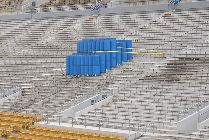
Figure 1. Configuration of drums for load test.
Load Testing of Strengthened Precast Double-Tee Beams
The presence of shear cracks near the dapped ends of 1,400 prestressed concrete double-tee beams in a parking garage led to questioning their structural adequacy. The structural analysis showed that the shear capacities of the double-tees were deficient and required strengthening to resist the design loads. Externally-bonded carbon fiber reinforced polymer (CFRP) laminates were selected for shear strengthening of the double-tees. Because of the novelty of the use of CFRP as a strengthening material at the time of this project, load tests of the strengthened members were required to demonstrate the CFRP efficiency. Twenty representative double-tees were selected for load testing.
The double-tees were tested following the cyclic load test protocol. Each load test was performed using the closed-loop method on two isolated, double-tee beams, loaded simultaneously, and using a steel beam to react against the existing inverted tee. Figure 2 shows the view of the top side with the hydraulic jacks used to apply the loads. The load and deflections were monitored using load cells and LVDTs, respectively. The load tests demonstrated the effectiveness of the CFRP strengthening system and the ability of the beams to carry their design loads.
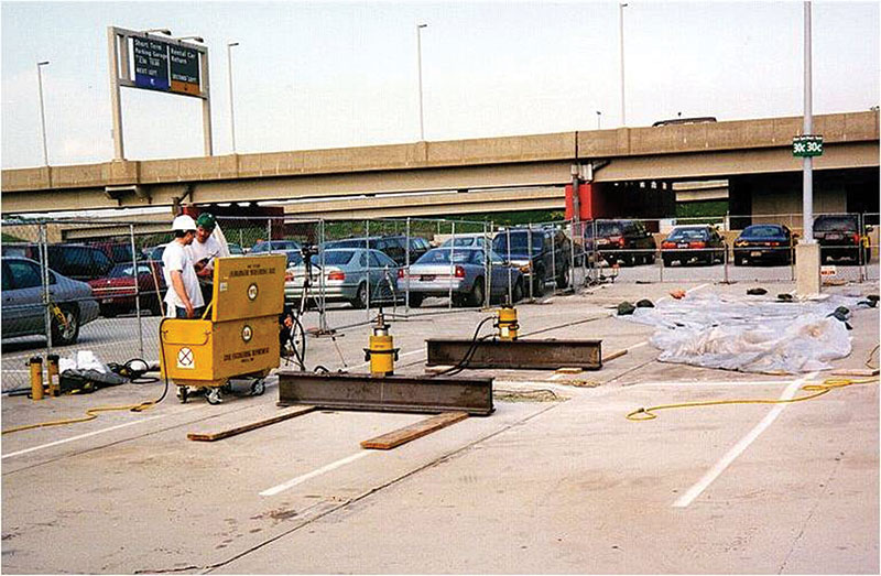
Figure 2. Hydraulic jacks on top of double-tees.
Load Testing of Strengthened Two-Way Post-Tensioned Concrete Slabs
The condition evaluation and structural analysis of the two-way post-tensioned concrete slabs of a parking garage revealed construction-related deficiencies that affected their structural capacity. These deficiencies were mainly related to incorrect placement of the tendons and mild steel reinforcement at the negative-moment regions, requiring flexural strengthening of negative and positive moment regions, and “punching” shear strengthening of slab/column intersections. Two strengthening alternatives were considered to address these deficiencies:
- Alternative 1: Construction of shear collars to enlarge the slab area to resist two-way shear around the columns. The shear collars can also reduce the flexural demands by reducing the clear span of the slab.
- Alternative 2: Installation of a CFRP strengthening system externally bonded to the slab topside at areas adjacent to the columns to increase the flexural and “punching” shear capacities of the slabs.
Preliminary cost estimates indicated that the cost of strengthening the decks using Alternative 2 would be about half the cost of Alternative 1. The time to construct Alternative 2 was also significantly less. In addition, Alternative 2 would result in further cost savings and reduced inconvenience to tenants because renting of offsite parking during construction could be reduced. Before determining the most suitable strengthening alternative, mock-ups of both alternatives were designed, constructed and load tested to confirm their effectiveness.
The load test program consisted of testing these two strengthening alternatives. Due to time constraints it was not possible to cast a concrete collar for the load test. Instead, the concrete collar was simulated by the use of steel shore posts uniformly around the column.
A cyclic-load-test protocol was used to load test a representative bay. A push-down test setup was used to create bending moments and shear forces along the negative moment region similar to that of a uniformly applied load. The test loads were generated by four hydraulic jacks, two on each side of the column that applied the load to the slab by means of a steel frame. The hydraulic loads reacted against the floors above to effectively push down the test slab. Figure 3 shows an overall view of the load test setup area.
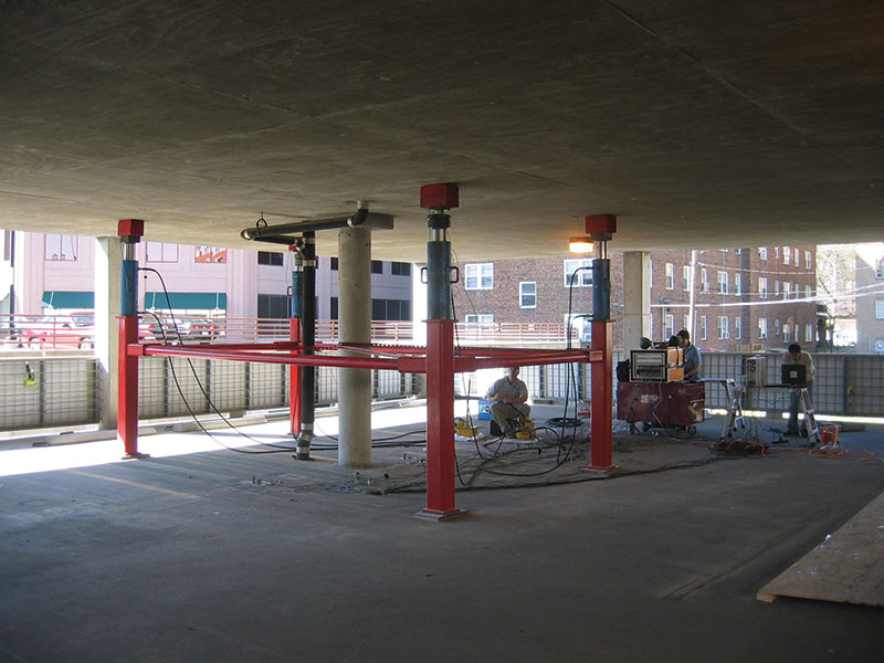
Figure 3. View of push-down load test setup.
During the load tests, the loads and displacements were continuously monitored by load cells and LVDTs connected to data acquisition equipment, which displayed the load versus deflection curves in real time. For the load test of Alternative 2, five strain gauges were installed on the CFRP laminates. The load tests demonstrated the effectiveness of both strengthening alternatives and the ability of the strengthened slabs to safely support the design loads.
Load Testing of the Lateral Load Resisting System of a Stadium
An initial study of a reinforced concrete stadium structure built in the early 1930s raised concerns that modifications to the masonry perimeter infill walls during a major renovation negatively impacted the lateral load-resistance of the stadium structure. The stadium is divided into 36 structurally-independent sections forming an oval shape. Each section consists of a system of reinforced concrete raker beams and deck beams supported by reinforced concrete columns, some of which are laterally braced by tie beams. The raker beams, in turn, support the concrete seating slab of the stadium structure.
The renovation project included removal of some of these infill masonry walls and enlargement of existing openings in a number of the infill walls to improve access to and from the stands. Certainly, these modifications changed the lateral load-resistance parallel to these walls, but their significance was not clear. Therefore, an in-situ lateral load-test was planned to evaluate the lateral load-resistance.
A cyclic-load-test protocol was used to load test a representative stadium section. Lateral loads were applied to the structure with hydraulic jacks placed along the column lines. The hydraulics were installed at an expansion joint between two adjacent sections of the stadium structure so that the two sections reacted against each other. During the lateral load tests, the applied loads and lateral displacements were monitored using load cells and LVDTs, respectively. Figure 4 shows the line of hydraulic jacks installed between the stadium sections for the load test and the LVDTs attached to fixed points.
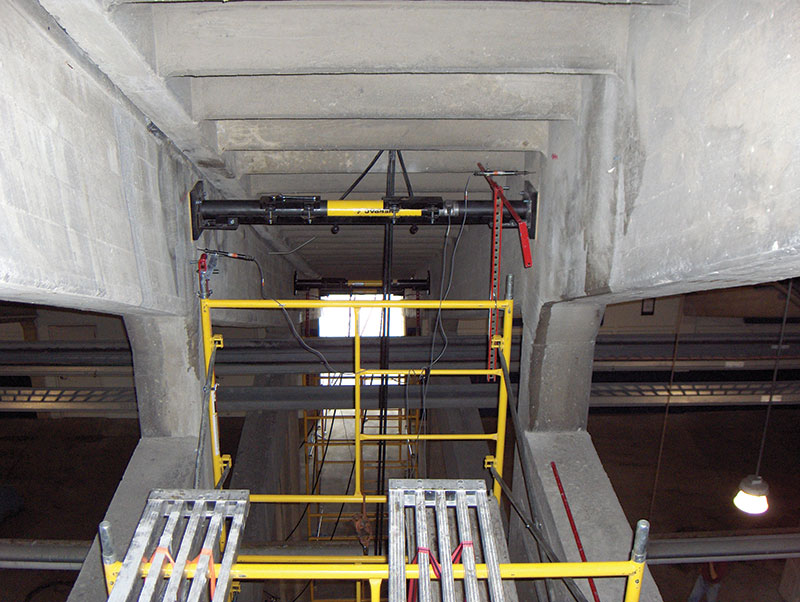
Figure 4. Hydraulic jacks and instrumentation between stadium sections.
The results of the in-situ lateral load testing provided information to create improved “calibrated” analytical models of the structure, including information on the in-plane behavior of the existing perimeter masonry walls. The improved models were used to estimate the lateral load demands on the frame elements (beams and columns) of various other stadium sections, due to load combinations including gravity and crowd-sway loads. The load test results and the structural analysis indicated that all the existing sections are adequate to resist the code-prescribed load and that the lateral load resisting systems did not require to be reinforced.
Final Thoughts
In-situ load testing is a valuable tool used in the evaluation and repair of concrete structures. Load testing is typically used to demonstrate that existing or repaired structures can safely resist design loads.
The recently published ACI 562 – Code Requirements for Evaluation, Repair, and Rehabilitation of Concrete Buildings and Commentary references ACI 437 for load testing of concrete structures. It is expected that once ACI 562 is adopted by the International Existing Building Code (IEBC) and local building codes, ACI 437 will become standard practice for existing concrete structures, whereas ACI 318 load testing protocol will remain applicable for structures under construction or structures that do not have a certificate of occupancy. It is also expected that after a transition time, the technical committees of ACI will adopt a unified set of loads and acceptance criteria applicable to any type of building.▪