
Components That Insulate Concrete and Steel Penetrations
Structural thermal breaks prevent condensation and mold, reduce heat loss through envelope penetrations, lower energy costs and carbon emissions, and reduce owner liability – while meeting increasingly stringent building energy codes.
Reducing energy usage in buildings has become a focal point of the architectural, engineering, and construction (AEC) industry to meet national energy goals and reduce costs to building owners. Heating, ventilation, and air conditioning (HVAC) contribute significantly to total building energy use, leading designers to pursue strategies for achieving better thermal performance.
The industry has responded with improved efficiency of HVAC systems and strengthened building envelopes via increased wall insulation and high-performance windows and doors. However, significant heat energy transmission through steel and concrete thermal bridges penetrating the envelope of otherwise well-insulated buildings is often overlooked.
That is changing as revised building energy codes directly address thermal bridging. An addendum to the American Society of Heating, Refrigeration, and Air Conditioning Engineers’ ASHRAE 90.1-2019, Energy Standards for Buildings Except Low-Rise Residential Buildings, specifically addressing thermal bridging and structural thermal breaks, is currently under review – a prelude to possible inclusion in future editions.
In 2020, New York City and Seattle became the first cities in the United States to mandate the mitigation of thermal bridging at concrete penetrations through the building envelope. In addition, major utilities offer financial incentives for builders and developers to improve energy efficiency by various means, including incorporating structural thermal breaks to strengthen the building envelope.
Mitigating Heat Transmission
The thermal conductivity of structural steel at beams, canopies, rooftop connections, and concrete that comprises a conventional pour-through balcony, for example, allows the rapid dissipation of interior heat into the exterior. The resulting energy waste can be minimized by installing structural thermal breaks at the building envelope between the interior slab or steel beam and the cantilevered or supported exterior structure. In addition, the risk of the interior structure near the thermal bridge reaching the dew point – which creates an ideal environment for condensation and mold growth – is eliminated.
Structural thermal breaks perform two functions:
- To minimize the transfer of heat across thermal bridges that penetrate the building envelope, and
- To maintain the structural integrity of the thermally broken connection and transfer loads between the interior and exterior structural elements.
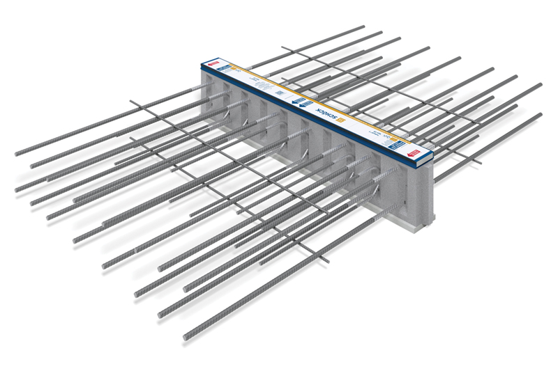
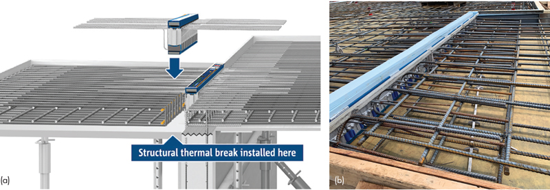
For concrete applications, manufactured structural thermal break modules (Figure 1) are constructed of polystyrene foam which is approximately 98 percent less conductive than concrete, and stainless steel rebar, which is approximately 67 percent less conductive than carbon steel rebar, reducing heat energy losses through balconies by up to 90 percent. Similar energy savings can be realized at slab edges, parapets, and other concrete envelope penetrations using structural thermal breaks (Figure 2).
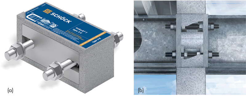
For steel applications, structural thermal break connections (Figures 3a and 3b) are comprised of insulated stainless steel modules and insulation fillers secured between steel end plates. The placement of the engineered structural thermal break between the endplates of the interior and exterior steel structure minimizes the conductive surface area, with only the load-bearing stainless steel bolts and HSS block of the structural module crossing the insulating layer. Again, the stainless steel rods conduct two-thirds less thermal energy than equivalent structural steel components.
As an alternative to a manufactured structural thermal break product for steel connections, bolted connections with thermal pads are often used to create a thermal break. For the pad connection to be effective, the pad material needs to be thick enough to break the thermal transfer – at least 1 to 3 inches (38 to 76 millimeters). Further, suppose the bolts are of structural steel rather than less conductive stainless steel. In that case, the net result may show little improvement or be worse than an unmitigated continuous beam through the building envelope. A benefit of thermal pads is that the pad material is inexpensive. The downside is that once the pad thickness increases to a level where it is thermally effective, the shear strength of the connection drops dramatically, requiring additional bolts and impacting thermal conductivity through the connection. In addition, there is the potential for degradation in the pad material and the potential risk of condensation.
Three Issues Resulting from Thermal Bridging
One issue resulting from thermal bridging is compromised occupant comfort. In a typical apartment where the balcony slab creates a thermal bridge, thermal imaging shows the cold creeping into the heated space, making the adjacent interior floors much colder than the rest of the floor. For example, an outside temperature of 32°F (0°C) and an interior temperature of 70°F (21°C) bring the temperature immediately next to the balcony door to a chilly 52°F (11°C). Cold floors and surrounding surfaces make a space less comfortable, which often means occupants bump up the thermostat to compensate.
Cold surfaces resulting from thermal bridging also lead to condensation buildup on interior surfaces. In modern construction using vapor barriers, the relative humidity of interior spaces during cold winter months ranges from 30 to 50%, versus approximately 25% in older buildings without vapor barriers. As a result, interior surfaces adjacent to thermally unbroken connections can cool to the dew point, causing condensation and supporting mold growth. In turn, this can damage the interior structure and finished surfaces and adversely affect air quality and occupants’ health, exposing the owner to liability.
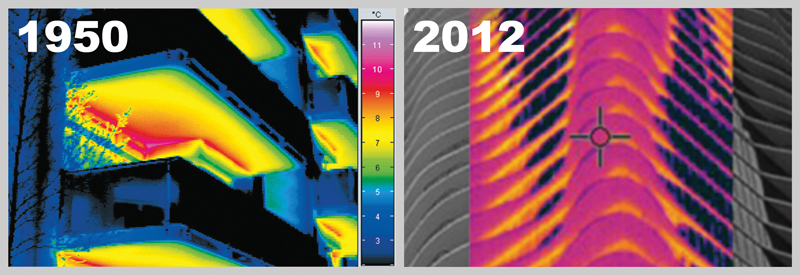
The third issue resulting from thermal bridging is significant heat loss. Thermographic images in Figure 4 show the effects of uninsulated thermal bridges on heat loss, comparing a typical building from the 1950s (left) to a more recent structure. Modern insulation efficiency has improved, yet uninsulated thermal bridges such as those found at balconies continue to be the path of least resistance for heat transfer. Thermal bridges significantly detract from the thermal performance of the surrounding insulated wall assemblies and can act as cooling fins to dissipate heat from the warm interior structure into the exterior environment.
Breaking the heat transfer pathway by incorporating a structural thermal break prevents cold surfaces from being introduced into the heated spaces, ensuring that thermal comfort is maintained and eliminating the risk of condensation and mold growth on interior surfaces. Also, a thermal break reduces heat loss through the insulated building envelope.
The Right Solutions
Structural thermal breaks have been designed for a wide range of concrete and steel structural connections and structural load conditions. In addition to balconies, structural thermal breaks can be incorporated at parapets, exposed slab edges, canopies, columns, concrete walls, and rooftop connections for mechanical equipment.
Concrete structural thermal breaks are manufactured in various heights to accommodate slab depth and, with various configurations of the steel reinforcement, to transmit bending moment and vertical shear forces. For buildings in seismic regions, supplemental modules that withstand lateral forces work in conjunction with those designed for bending moment and vertical shear.
Steel structural thermal break modules are used to resist compression, tension, and shear forces. Modules acting together in tandem resist moment forces for a cantilevered beam connection.
When incorporating structural thermal breaks into a building project in North America, the manufacturer is responsible for designing the thermal break connections. The project structural engineer should ensure that the structure surrounding the connection is designed to receive the loads transmitted by the structural thermal break adequately.
In addition to design services, manufacturers commonly provide resources for ensuring a seamless design and installation process, including CAD/BIM details and models, specifications, continuing education courses, and case studies.
Installation in Concrete Applications
Installing structural thermal breaks for concrete applications is simple (Figures 5a and 5b). For example, for a mild reinforced concrete condition, the installers typically construct the interior rebar cage, leave a seven-inch gap, then construct the exterior rebar cage. The structural thermal breaks are placed in the gap, end to end, and tied into the rebar cages on each side. The team can then proceed with one continuous concrete pour of the interior and exterior slabs.
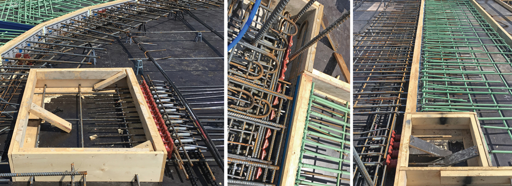
Using structural thermal breaks with post-tensioned (PT) slabs is also possible with some advanced planning regarding the placement of the PT tendons. Figure 6 shows one PT layout design method to avoid intersecting the structural thermal breaks. A small box is isolated for accessing the live ends. After tensioning, rigid insulation is placed continuously with the adjacent structural thermal breaks, and the box is filled with high-performance grout.
Structural thermal breaks can also be installed into precast concrete applications.
Tower at PNC Plaza Example
The 33-story LEED Platinum Tower at PNC Plaza (Pittsburgh, PA) has been touted as the “world’s greenest office tower.” It was designed to consume about half the energy of conventional structures of equivalent size, thanks mainly to a ventilation system that takes advantage of seasonal temperatures when advantageous and insulates against them when not.
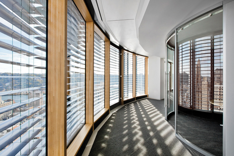
The key element of the energy-saving system is a double-skin façade consisting of an interior and an exterior glass curtain wall (Figure 7). For nearly half of the year, during spring and fall, the building ventilates as fresh air flows through actuated vents in the exterior façade into the space between the curtain walls and through two vertical thermal shafts and a solar chimney, warming or cooling the interior space passively.
During summer and winter, the building reverts to conventional mechanical heating/cooling, requiring continuous insulation of the interior façade wall, including thermally breaking the concrete slab extensions supporting the exterior façade wall.
The design team specified Schöck Isokorb® concrete-to-concrete structural thermal breaks for the cantilevered concrete slabs. There is one mile of these thermal breaks on 30 floors, installed linearly along the junction of the inner curtain wall and building core.
Benedict Tranel, Principal at Gensler Architects and Project Architect on the Tower, says, “The inner façade of the building is like the insulation layer in a jacket while the outside glass façade is like the outer GORE-TEX® fabric layer.” Hao Ko, design director of Gensler Architects, adds, “Without the thermal breaks, it would be like wearing a down jacket but leaving it unzipped.”
The Tower has won the R&D Award for High-Performance Buildings, received LEED Platinum certification, and set a new benchmark for energy efficiency and sustainability.
U.S. Bank Stadium Application
In Minneapolis, the U.S. Bank Stadium wows visitors with its striking asymmetrical shape, transparent roof, acres of glass, 95-foot-high (30 meters) pivoting glass doors, and an enormous asymmetrical video board (Figure 8).
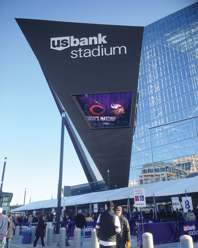
The unconventionally large and heavy video board is supported by structural steel tubes cantilevered from the steel framework within the heated building envelope. Sitting 150 feet (45 meters) above grade on the exterior of the western prow, the behemoth board weighs 45,000 pounds (20,400 kilograms).
The challenge was the thermal conductivity of the structural steel supporting the board. The board connects to an exterior metal panel, behind which sits an array of metal studs with an insulated waterproofing barrier – all surrounded by a steel superstructure. The high thermal conductivity of steel increases thermal bridging between Minnesota winters’ sub-zero temperatures and the supporting steelwork’s heated interior. “It was imperative to prevent cold exterior steel from touching warm interior steel and causing a thermal bridge,” said Eric Grusenmeyer, Project Engineer at Thornton Tomasetti.
The design team specified Isokorb structural thermal breaks for steel-to-steel construction. The thermal break products are equipped with flanges and bolts for fastening to flanged rectangular steel tubes on the interior side and to opposing flanged steel tubes supporting the video board on the exterior side.
The resulting assembly reduces heat loss through the penetration by up to 50%, reducing heat energy costs and heating system capacity requirements accordingly. Most importantly for the video board application, they prevent the interior side of the supports from becoming cold, reaching dew point, and forming condensation, which could compromise the surrounding structure and incur ongoing maintenance costs.
According to Lance Evans, Principal and Senior Vice President for the architectural firm HKS, which designed the stadium and board, “Our design had to address severe Minnesota weather conditions. Outside temperatures can dip to more than 20 degrees below zero, while the stadium must maintain a comfortable temperature for the people inside. Preventing thermal bridging was essential to ensuring the integrity and performance of the stadium structure. The structural thermal breaks provided an effective barrier to accomplish that task.”
Conclusion
Concrete and steel structures penetrating the insulated building envelope provide a conductive pathway for interior heat energy to dissipate into cold exterior environments, adversely affecting owners, tenants, and the environment.
Thermal breaks installed at the building envelope maintain the structural integrity of steel and concrete penetrations while reducing the escape of heat energy by up to 50 and 90 percent, respectively, preventing interior condensation and mold, improving the comfort of occupants, complying with stringent building codes, and contributing significantly to sustainability goals.■
References
Morrison Hershfield, Report No. 5131042.00, Thermal Break Technology for Various Construction Types
www.schoeck.com/view/6047/Morrison_Hershfield_Report_Thermal_Break_Technology_for_Various_Construction_Types__6047__.pdf/en-us
Breaking Up Is(n’t) Hard to Do, Geoff Weisenberger, American Institute of Steel Construction, page 3
www.aisc.org/globalassets/modern-steel/archives/2018/09/breakingupisnthardtodo.pdf
RDH Building Engineering Ltd, Report #1 Impact on Effective R-Values and Energy Code Compliance,
www.rdh.com/wp-content/uploads/2017/07/Part-1-The-Importance-of-Slab-Edge-Balcony-Thermal-Bridges.pdf