
An Economical Solution for Non-Ductile Frames
Many older buildings include columns that require strengthening. Several scenarios could cause this. In coastal regions and aggressive environments, for example, the corrosion of reinforcing steel results in loss of capacity of the columns. In other cases, the poor quality control during the original construction may have resulted in low compressive strength in the concrete. The author has been personally involved with the retrofit of two such buildings in Florida, where the concrete compressive strength has been below 1500 psi, only a fraction of the strength specified in the design documents. Some of the collapsed Champlain Tower investigations in Surfside, Florida, have also mentioned the “powder-like” concrete in the columns as a potential contributing factor to that failure.
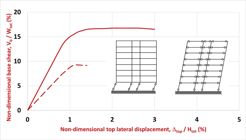
In yet another scenario, before the late 1970s, concrete frames were commonly designed with the beams being stronger than the columns. When subjected to lateral forces, for example, during an earthquake, plastic hinges can form at the ends of such columns. In the worst case of weak columns, flexural yielding can occur at both ends of all columns in a given story, leading to the column sway mechanism and collapse of the building. This is shown with the dashed line in Figure 1. In contrast, when the flexural capacity of the columns exceeds that of the beams, the failure of the frame is more ductile (beam sway mechanism), as shown with the solid line in Figure 1. A large number of plastic hinges that can form at the ends of the beams dissipate significant energy, leading to a more desirable ductile failure. In 1983, in recognition of this behavior, ACI-318 required the ratio of the sum of the flexural capacities of the columns to those of the beams to be larger than 1.2. It is well recognized that keeping this ratio even larger than this specified minimum improves the frame’s overall performance.
Many older buildings in seismic regions constructed prior to the early 1980s fail this test and have been designated non-ductile structures. For example, in Los Angeles, over 1300 buildings are the subject of an ordinance called Mandatory Earthquake Hazard Reduction in Existing Non-Ductile Concrete Buildings. These building owners must retrofit their structures and address these shortcomings over a 25-year time frame that began in late 2017.
This article provides a new solution for enhancing both the axial and flexural capacity of such columns. Implementing the technique is relatively easy, leading to a fast and economical solution with minimal disruption to the occupants. An additional feature of the repair is its small footprint, which minimizes floor space loss due to such modifications.
Fiber Reinforced Polymer Solutions
The author introduced the concept of repair and strengthening of structures with Fiber Reinforced Polymer (FRP) products in the late 1980s. In that original approach, known as a wet layup, sheets of carbon or glass fabric are saturated in the field with epoxy. They are bonded to the external surface of the structural element, such as beams, columns, and walls. Within several hours, the materials harden and reach a strength 3 to 4 times that of steel. In addition, the FRP serves as additional tension reinforcement that can contribute to the flexural and shear resistance of the host structure. Numerous applications of this system over the past two decades attest to the advantages of these products.
Most of these applications have been for flexural and shear strengthening of beams. In such cases, the maximum moment is typically at midspan, and there is sufficient distance to the end of the span to develop the full capacity of the FRP. On the other hand, applications of wet layup FRP in columns have been chiefly for confinement and shear strengthening. The maximum bending moments in columns occur at the floor levels. Because FRP cannot be easily extended through the floors, it is difficult to achieve significant axial and flexural enhancement of columns with these products. Furthermore, externally bonded FRP does not increase the stiffness of the column that much. This contrasts with the strengthening of beams, where there is appreciable gain in stiffness of the member after FRP is applied. These shortcomings can be overcome using relatively new FRP laminates.
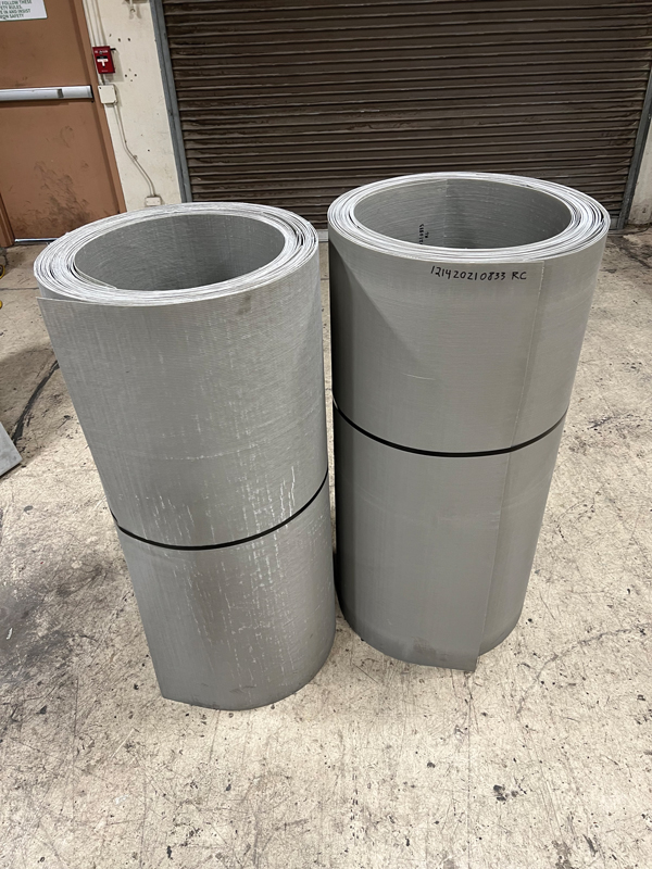
Over a decade ago, the author introduced a new type of FRP laminate with applications in strengthening columns or piles and pipes. These laminates are constructed with specially-designed equipment. Sheets of carbon or glass fabric up to 9 feet wide (2.7m) are saturated with resin and passed through a press that applies uniform heat and pressure to produce the laminate (Figure 2). The laminates offer several significant advantages compared to the fabrics used in wet layup applications, as listed below:
a) Using a combination of unidirectional and/or biaxial fabrics, the laminates provide strength in both longitudinal and transverse directions; the tensile strength of these laminates can reach 155 ksi (1070 MPa).
b) The laminates can be made as thin as 0.03 inches (0.76 mm); this allows them to be bent around a corner with a radius of 2 inches (50 mm) (Figure 2).
c) The laminates are manufactured in plants under high-quality control standards; this improves the quality of the finished construction.
d) The strength of the laminates can be tested before installation; this assures the design engineer that the specified strength is met, eliminating delays for corrective actions.
e) The repairs can be completed much faster in the field.
f) The number and pattern of the layers of fabrics in the laminates can be adjusted to produce an endless array of customized products that can significantly save construction time and money.
Since the introduction of this system, many agencies have conducted independent tests to verify the efficacy of these laminates for a range of applications. These include a study funded by the National Science Foundation (NSF) and Caltrans for fast repair of earthquake-damaged bridge piers, a study funded by the Nebraska Department of Roads for strengthening deteriorated timber bridge piles, and another funded by the Texas DOT for the repair of corrosion-damaged steel H piles. However, the most significant investigation was a 3-year study by the U.S. Army Corps of Engineers, which resulted in the military selecting a laminated product to repair submerged piles worldwide. In addition, the U.S. Navy’s website reported that the product was used to repair concrete piles in Ukraine (www.tinyurl.com/PLM-UKR). The U.S. Army Corps of Engineers and the Federal Emergency Management Administration (FEMA) have also singled out these laminates in their 2013 Field Operations Guide as the selected product for repairing columns and piles that may be damaged in a disaster, including hurricane, earthquake, terrorism, and more.
A proprietary system was developed to use these laminates to construct a shell around the column to create a small annular distance. Reinforcing bars can be placed within this cavity before filling with concrete or grout. The jacket serves as a stay-in-place form that facilitates the construction process and provides significant shear reinforcement and confinement for the column.
Design Example
The following example illustrates the application of this technique to retrofit non-ductile frames. The existing frame (Figure 3) consists of an 18-inch x 18-inch square column, reinforced with eight No. 8 bars. Lateral reinforcement is No. 4 at a 12-inch-spacing along the column height. For simplicity, it is assumed that beams in both directions are 14 inches wide x 26 inches high, and they are reinforced with a pair of #10 bars at the top and bottom. Concrete compressive strength is 4000 psi, and steel reinforcement is Grade 60.
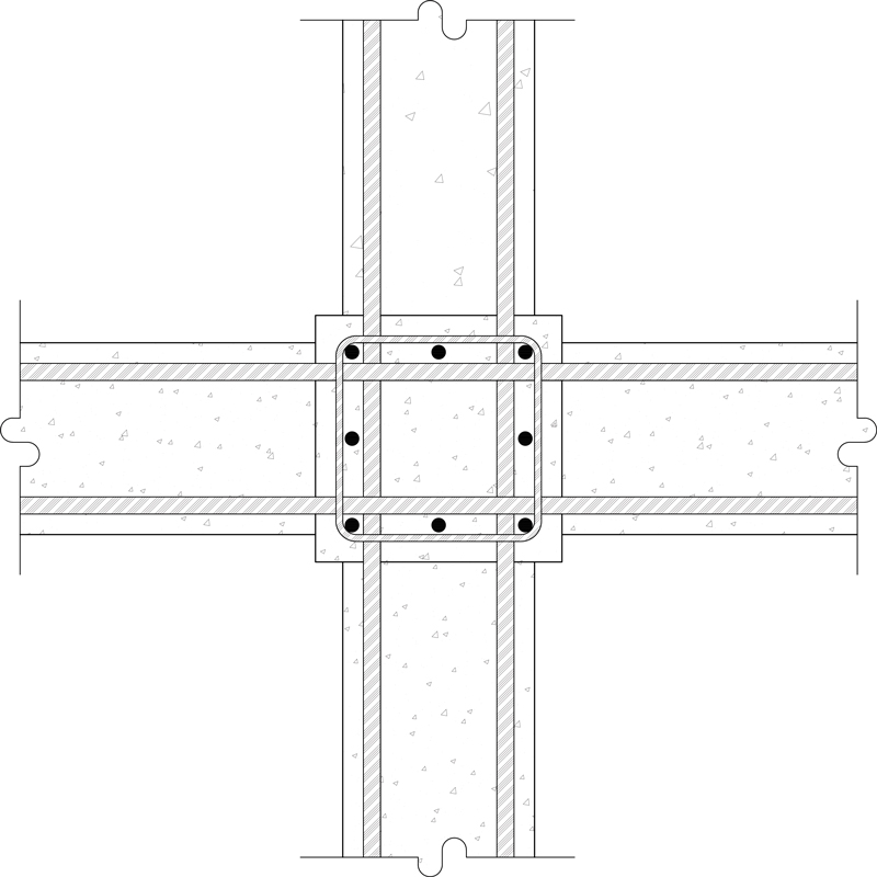
The nominal moment capacity of the column is Mcol = 219 k-ft, and for the beams is Mbeam = 276 k-ft. Therefore, the flexural strength ratio, MR, can be checked as:
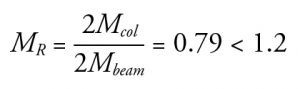
This ratio does not meet the minimum value of 1.2 set by today’s standards and requires flexural strengthening of the column. The corners of the column that do not include any reinforcing steel can be cut and removed to minimize the enlargement of the column and loss of floor space. Two new No. 8 bars can be placed at each corner, and these bars extend to the floor above through the slab. Plastic spacers are installed on the column to define the annular space. In this example, 1.5-inch-long spacers are placed in the middle of the column sides (Figure 4).
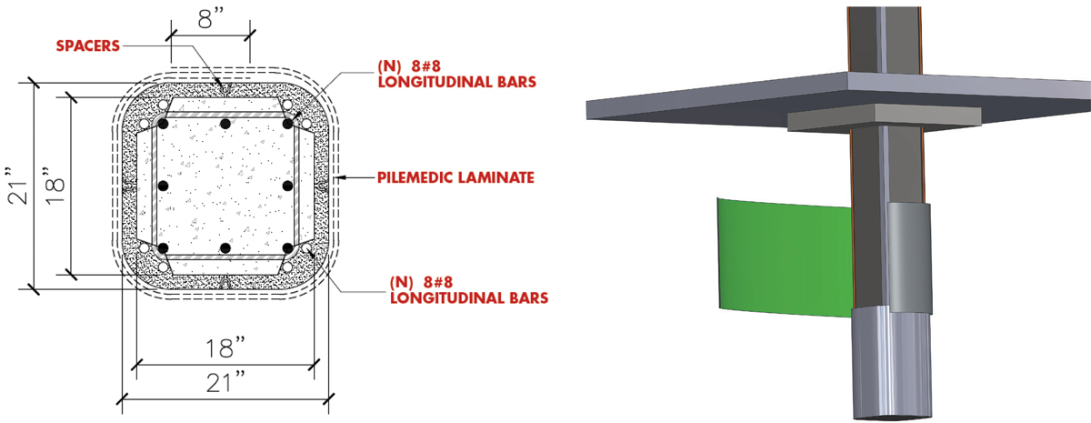
In this case, PileMedic® laminates are supplied in 4-foot-wide rolls to any desired length (Figure 2). These laminates are 2 to 3 times stronger than steel. Typical detail requires the laminate to be wrapped two complete times plus an 8-inch overlap around the column (Figure 4). The laminate is cut to the desired length, and an epoxy paste is applied; the laminate is wrapped around the column and bonded to itself to create a 2-ply shell at a distance of 1 to 2 inches from the face of the column (Figure 4). Additional 4-foot laminates are similarly installed and overlap the previous shell by 3 to 4 inches to cover the full height of the column. Finally, the annular space between the column and the PileMedic jacket is filled with concrete or grout using a pump or the tremie method.
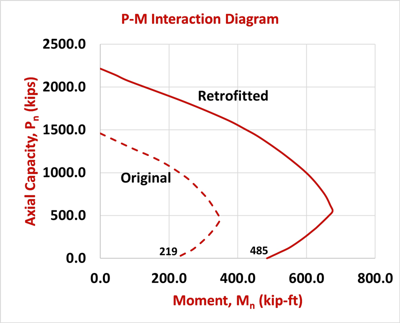
The interaction diagram for the retrofitted column has been calculated and is compared to the original column in Figure 5, assuming the grout strength to be 4000 psi. The axial capacity of the column has been enhanced, but its flexural capacity has also been increased to 485 k-ft. Therefore, the flexural strength ratio for the retrofitted frame is:
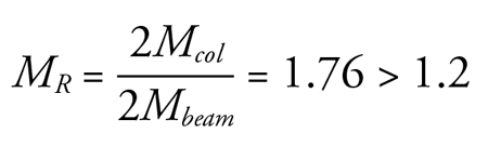
This is significantly larger than the minimum value of 1.2 and ensures that any plastic deformations are concentrated at the beam ends. Furthermore, in the above calculations, the increase in compressive strength of the concrete in the column due to confinement by the FRP shell was conservatively ignored. Thus, the actual increase in flexural capacity of the column is even higher than presented in this example.
The jacket is a stay-in-place form that expedites construction, but it also acts as supplementary steel ties, which is a shortcoming in these columns. The laminate provides the equivalent of No. 4 ties at a spacing of 3 inches which is far stronger than the original design. Depending on the type of laminate used and the number of wraps (2 or more), this contribution can be increased even more. In addition, the confinement provided by the shell increases the compressive strength of the original column and the newly placed grout and the ductility of the column. Lastly, the impervious FRP shell prevents moisture and oxygen ingress in corrosive environments and significantly lowers the column’s corrosion rate, prolonging the structure’s life. The FRP itself is non-corroding, so any future rain or moisture simply runs off the surface without causing any damage to these jackets.
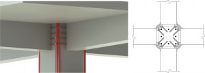
For the joint region within the depth of the beam, steel ties can be epoxy anchored into the core of the column to provide support against buckling for the newly installed longitudinal column bars (Figure 6). This region can subsequently be encased in concrete. Spacers have been developed that ensure the proper width of the annular space. These can also hold the longitudinal column bars in the desired location (Figure 7). The beam-to-column connection must be checked, which may indicate a need for an enlargement of that region. However, an earlier study has demonstrated that as the flexural strength ratio increases, the required lateral ties in the joint region may be relaxed.

The footprint of the proposed retrofit is very small. In this example, the column dimensions were increased by only 3 inches, while the flexural capacity of the column was more than doubled. The entire system is comprised of lightweight materials that can be taken to any floor of the building using passenger elevators. The estimated cost to retrofit a typical column is well below $10,000.■
References
Dawood, H., H. Karagah, C. Shi, A. Belarbi, and C. Vipulanandan. 2015. “Repair Systems for Deteriorated Bridge Steel H Piles,” Final Report Submitted to Texas DOT, Technical Report o-6731-1, University of Houston, December 2015, 538 pp.
Ehsani, M. 2010. “FRP Super Laminates: Transforming the Future of Repair and Retrofit with FRP,” Concrete International, American Concrete Institute 32(3): 49-53.
Ehsani, M. 2018. Reinforcement and Repair of Structural Columns, U.S. Patent #9,890,546.
Ehsani, M. 2020. Spacers for Repair of Columns and Piles, U.S. Patent #10,908,412.
Ehsani, M.R. and J.K. Wight. 1990. “Confinement Steel Requirements for Connections in Ductile Frames,” J. of Struct. Eng. Div., ASCE, 116(3), 751-767.
“Field Operations Guide,” 2013. U.S. Army Corps of Engineers Urban Search and Rescue Program, 7th Edition, June 2013, (pages 4-4 to 4-5)
Gull, J.H., A. Mohammadi, R. Taghinezhad, and A. Azizinamini. 2015. “Experimental Evaluation of Repair Options for Timber Piles,” Transportation Research Record, TRB, Washington, D.C., 2015, pp.124-131, DOI: 10.3141/2481-16
Hammons, M.I., J.S. Strickler, J.W. Murphy, C.P. Rabalais, C.K. Crane, and C. Barela. 2018. Pile Wrapping for Expedient Port Repair – PIER Spiral 1, Engineer Research and Development Center, U.S. Army Corps of Engineers, Draft Report, August 2018, 117 pp.
Saadatmanesh, H. and Ehsani, M.R. 1990. “Fiber Composite Plates Can Strengthen Concrete Beams,” Concrete International, 12(3), 65-71.
Yang, Y., R. He, L. Sneed, M. Saiidi, A. Belarbi, and M. Ehsani. 2015. “Emergency Repair of a RC Bridge Column with Fractured Bars using Externally Bonded Prefabricated Laminates – An Experimental Study,” Composite Structures, Elsevier, 133(2015), pp. 727-738