
Boston University Center for Computing & Data Sciences Building
The Center for Computing & Data Sciences is a dynamic new vertical campus building at Boston University. The design maximizes opportunities for interaction and interconnectivity and carefully integrates every element to establish Data Sciences as Boston University’s new iconic heart.
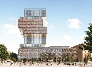
The 19-stories-tall, 345,000-square-foot facility will be the University’s tallest and the largest 100 percent fossil-fuel-free building in Boston, Massachusetts. Targeted to attain LEED Platinum, the building incorporates several high-performance sustainability features. The state-of-the-art building, designed by KPMB Architects of Toronto, Canada, will be home to the departments of Mathematics & Statistics, Computer Science, Computing and Data Sciences, and Computing and Computational Science & Engineering.
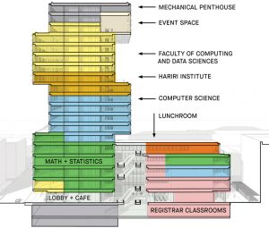
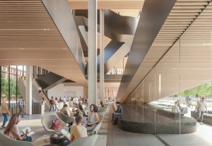
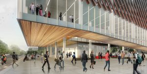
Located in the heart of the campus at the corner of Commonwealth Avenue and Granby Street, along the Charles River, the building is designed to be socially sustainable, putting the people it serves first. It is an open, welcoming building that encourages interaction, collaboration, and movement to enhance the student’s experience. The building design provides a walkable vertical campus with the tower organized by a series of vertically stacked and staggered research “neighborhoods,” each with access to an outdoor green-roofed terrace, linked by an interconnecting feature stair encouraging faculty and students to walk the building.
The building will be a hub for the campus and a model for future building design, sustainability, and resiliency. It sets the direction for meeting Boston University’s Climate Action Plan goals for new construction and achieving net-zero carbon emissions for the University by 2040. A key component of BU’s strategy is switching from fossil fuels and relying primarily on electricity generated from renewable sources. The building and systems are designed to minimize energy consumption and use ground-source heat pump “geothermal” for heating and cooling. Efficiency begins with the building enclosure incorporating, in this case, a triple glazed curtainwall to keep heat in during the winter and external sun shading to reduce solar heat gain in the summer. Mechanical systems designed by BR+A utilize high-efficiency systems, including active chilled beams, dedicated outside air systems, and heat recovery. The geothermal system, designed by Haley and Aldrich, consists of thirty-one 1,500-foot-deep bores connected to the heat pump chillers. The closed-loop system will draw heat from the ground in the winter and expel heat in the summer and is the primary source for heating and cooling. The result of these efforts is zero operating carbon. The Center for Computing & Data Sciences aligns with the American Institute of Architects 2030 Challenge goals for new buildings to be operationally carbon-neutral by 2030.
Embodied carbon is the other critically important component of the carbon equation representing the carbon associated with infrastructure development. Embodied carbon includes the carbon dioxide equivalent for all phases of a building’s life cycle, starting from initial material extraction and building product fabrication, construction, repair, and refurbishment during the building’s use, and, finally, end-of-building life, like demolition or product reuse and recycling. For a typical new building, structural and enclosure systems represent more than half of the total embodied carbon, with the structural system being dominant. This is primarily due to the materials those systems employ, which require a tremendous amount of energy and resources to produce. For operational carbon efficient buildings, the embodied carbon represents a significant portion of carbon associated with the building.
Embodied carbon in buildings is not a new concept, but attention has increased in recent years. With the urgency of addressing climate change and the recognized need to reduce total carbon drastically, it is imperative that the education, advocacy, and innovations associated with embodied carbon advance rapidly. A movement is happening around addressing embodied carbon and finding ways to reduce it that is gaining momentum. One challenge structural engineers face is the assumption that the structure cannot contribute to achieving sustainability goals and embodied carbon reductions. However, that has begun to change as a new focus and understanding of embodied carbon of structural and enclosure systems has begun. A strong signal of this change is the SE 2050 Commitment Program (SE 2050), launched in November 2020 by the Structural Engineering Institute (SEI) of the American Society of Civil Engineers (ASCE). Developed in response to the SE 2050 Challenge issued by the Carbon Leadership Forum (CLF), the goal is that “All structural engineers shall understand, reduce, and ultimately eliminate embodied carbon in their projects by 2050.” The SEI Board of Governors unanimously endorsed the vision of SE 2050 in December 2019. As of March 2022, over 75 structural engineering firms have signed up for the Program.
One of the project’s sustainability goals was to achieve a USGBC LEED Platinum rating status. LEED BD+C: New Construction v4.1 (LEED v4.1) presents opportunities to address embodied carbon from a structural and enclosure standpoint that directly contribute to the rating point total. Using the LEED v4.1 through the Materials and Resources Credit (MR Credit): Building Impact Life-Cycle Impact Reduction Option 2, the project can achieve four points by performing a Whole Building Life-Cycle Assessment (WBLCA) that demonstrates at least a 20% reduction in embodied carbon (also known as Global Warming Potential) when compared to a typical baseline building. This path requires a minimum of 10% improvement in two additional environmental impact categories. The WBLCA requires a cradle-to-grave life-cycle assessment of the project’s structure and enclosure systems; therefore, the total reduction from baseline includes the summation impacts of both systems.
In considering options for addressing embodied carbon of both the structure and enclosure, the design team determined that, since the design of the enclosure system was for optimal operational carbon, gains in embodied carbon efficiency would not outweigh potential losses in operational carbon efficiency by making design changes to the enclosure. Therefore, the design team concluded that the structure would be the primary system of focus for embodied carbon reductions. They presented options during early design sustainability charrettes, including adjustments to the structural system related to both structural material quantity reduction and material design and specification. Approximate embodied carbon reductions of the various options were outlined in conjunction with corresponding cost, schedule, and availability topics. Working with KPMB and The Green Engineer, the project’s sustainability consultant, an evaluation of potential MR Credit points was reviewed. With strong support from Boston University, the design team was challenged to continue to explore and implement embodied carbon reductions wherever possible. This effort went for embodied carbon beyond what is tracked in LEED v4.1, with the design team specifying, for example, some of the lowest embodied carbon flooring materials available on the market, attention to the embodied carbon of the chosen furniture elements, and a wood biophilic design approach using FSC certified products.
For the steel portion of the structural system, the design team worked closely with the general contractor, Suffolk, and the steel provider, Canatal, which was engaged early as a design-assist partner, to minimize the system’s environmental impact. Minimum truss connection material, optimal splice locations, minimizing crane picks and field welding, and optimizing member sizes while considering availability and shipping distances were evaluated. This process removed several tons of structural steel from the project beyond the typical efficiencies expected from a conventionally steel-framed system. The design team evaluated the use of higher grades of steel for columns, up to Grade 70, to further reduce steel tonnage. However, for various project constraints, the decision was made not to use the higher steel grades. Finally, consideration of the steel production, a significant contributor to embodied carbon of steel products, was evaluated and options outlined to source the steel from the least impact production sites in North America.
For the concrete portion of the structural system, two primary areas of focus were explored – minimizing total portland cement content in the concrete mixes and minimizing the use of lightweight concrete. The production of portland cement is responsible for approximately 5%-10% of the world’s CO2 emissions and makes up 80-90% of concrete’s total embodied carbon impact. Minimizing the use of portland cement is critical in making substantive reductions in embodied carbon.
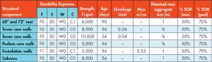
In Boston, concrete mixes have an average portland cement replacement rate of approximately 20%, primarily replacing portland cement with supplementary cementitious materials (SCM) of fly ash, slag cement, silica fume, or a combination of the three. In general, replacing portland cement reduces the heat of hydration of the mix and thus can modestly increase set times; therefore, extensive discussions related to construction sequence took place early on. With support from Boston University, the design team explored options to replace all concrete on the project except concrete for flatwork at much higher rates than typically seen in the area. Working with Suffolk, the design team presented preliminary concrete mix design goals to two local concrete suppliers. The data shown in Table 1 was used primarily for conversational purposes with each supplier to describe the replacement rate goals and allow for a fruitful discussion around availability, available test data, anticipated set times, shrinkage, and other considerations. A derivative of this table, following these initial discussions, was included in the Contract Documents. Another option would have been to specify the embodied carbon limits for each component instead of using the percent SCM as a proxy for reduced embodied carbon. Unfortunately, available third-party verified Environmental Product Declarations (EPDs) documenting embodied carbon of mixes were limited at the time of design. The team proceeded with using percentage SCM as the method of specification.
Each supplier brought to the conversation important available test data, a plan for running project-specific trial batch mixes, a review of set time, mix constituent availability, and cost. Through the early collaboration with local suppliers, the design and construction teams were able to identify achievable goals for each structural component of the project and evaluate against the total embodied carbon of the WBLCA to further inform the Owner. These early conversations allowed the design team and contractor to review impacts on the overall project schedule and evaluate options for where to make adjustments. Extensive discussions revolving around the timing of form stripping and application of temporary construction loads factored into selecting appropriate mix designs. Through early engagement and subsequent dialogue throughout the procurement and installation process, the project employed concrete with portland cement replacement rates of up to 70%, the highest ever used in Boston for this type of application. This yielded some mixes with a nearly 30% reduction in embodied carbon.
LeMessurier performed the WBLCA using Tally and worked with The Green Engineer for incorporation into the LEED certification application process. With the design modifications to the steel and concrete products, a 9% reduction in structural and approximately 6% of total embodied carbon was achieved compared to the baseline structural and enclosure systems, equating to an approximate savings of over 1.14×10^6 kg of CO2e or approximately 1,300 tons. If accepted by the USGBC LEED reviewers, this will provide the project with 2 additional points through the MR Credit.
It should be noted here that the portland cement replacement for such a study typically uses the published regional averages from the National Ready Mix Concrete Association (NRMCA), in this case approximately 20% for baseline concrete in Boston. This was done for most of the concrete elements; however, for the large concrete mat foundation, it was not felt that using 20% would have been appropriate. For this element, designers used 40% for a baseline portland cement replacement given that is what is typically done for mat foundations of similar geometry in the Boston market, primarily to keep the heat of hydration down for constructibility, etc. Had a 20% baseline number be used, the improvement shown would have been higher than 9% which, in the designer’s opinion, did not appropriately reflect the intent of the LEED credit.
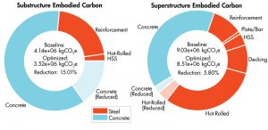
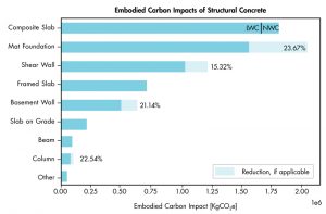
Figure 1 shows the breakdown of total embodied carbon for the substructure and superstructure. Over two-thirds of the contribution is in the superstructure, given the amount of structural steel and lightweight concrete. However, the primary reductions focused on concrete components of the substructure. Figure 2 further breaks down the concrete components identifying where specific reductions were achieved.
The construction schedule required removing the formwork on some elements earlier than anticipated during initial planning and slightly reduced the amount of embodied carbon savings. The request resulted in a modest amount of concrete that required a lower replacement rate than previously assumed. Understanding the importance of embodied carbon reduction, Suffolk requested a review of the WBLCA before proceeding with the change to ensure at least a 5% reduction was maintained, which was only possible with early all-inclusive planning discussions. Ultimately, the total savings was not reduced below 5%.
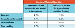
Although not required for certification, there were several reasons for performing a post-construction WBLCA analysis. First, it allowed the design team to compare the impacts of the designed and documented quantities versus the ‘real’ delivered-to-site quantities. Second, it allowed the design team to validate design assumptions and generally continue improvement in evaluating environmental impacts. For example, steel tonnages were assumed to increase by 5% to account for standard connection material and 10% for the large truss connections. Third, it provided valuable information on what impacts might exist but are not required to be assessed by LEED based on means and methods of constructing the structural and enclosure systems or nonstructural components like concrete site walls and landscape elements. The differences shown in Table 2 are a straight comparison between what the team modeled in Revit versus what was delivered to the site, with differences ranging between 12.6% and 14.9%. These differences were adjusted to account for actual delivery quantities but were not part of the base building structural system, such as the tower crane mat foundation or the temporary steel shoring columns used to support the trusses during erection. The adjusted values of concrete, concrete reinforcement, and structural steel dropped to 8.3% to 10.8%. Having such numbers will help better inform design assumptions and, if tracked on subsequent projects, will continue to improve the accuracy of future WBCLAs towards understanding actual impacts.
This project yielded relatively significant reductions in the structural system’s embodied carbon, which would only have been possible with solid support and a challenge from the Owner. Boston University leadership was the key to success and allowed the design consultants to engage in essential and frequent dialogue with the sustainability consultant, contractors, and product suppliers. Throughout this process, there were many lessons that all parties learned from and will successfully employ on future projects.■