
Creative Solutions for a National Historic Landmark
Nestled between university housing and hospitals in Madison, WI, is a building that, even among equals, distinguishes itself as a monument to architecture. A National Historic Landmark, the First Unitarian Society Meeting House was designed by Frank Lloyd Wright and completed in 1951. The building’s auditorium is supported by center-hinged wood trusses spanning up to 76 feet near the entrance, down to 12 feet at the building’s iconic prow. Trusses bear on stone piers and walls. Wright restricted himself to using 2×4s and occasionally 2×6s. The contractor later commented that Wright wanted to “build that church with toothpicks,” a statement that would become apparent over the next 60 years.
Within 10 years, the longest spanning truss (“truss J”) had settled noticeably. In 1961, a 1-inch-diameter steel cable was added to tie the bottom ends of truss J together. Though the concept was sound, the cable attached to the side of the truss and the 9-inch eccentricity forced the truss out of plane as it settled further.
Pierce Engineers (PE) studied the auditorium structure, historical documents, and past repairs to recognize the underlying issues. Nonlinear FE modeling of the entire structure indicated that Wright’s structure was severely under-designed even when compared against decreased and more realistic roof loads. The structure’s stability, though fragile, pointed to the load-sharing ability and redundancy in the structural system. For example, roof sheathing stresses in the FE model suggested their heavy involvement in load-sharing, likely due to construction sequence. Trusses were constructed before the load-bearing stone and were supported by wood shoring until the roof sheathing and stonework were completed. This sequence engaged the purlin/sheathing along truss top chords, contributing to truss strength and stiffness.
The simplest solution to address truss settlement would have been to add a new steel truss. However, removing a portion of the roof to install a new truss was rejected due to concerns of disrupting the roof sheathing’s contribution to load-carrying capacity. Removing a portion of the ceiling to raise the truss into place was not an option since the auditorium needed to be functional during repairs. Only a 30- x 48-inch opening in the ceiling was available, and work needed to be completed in a dry attic with wood framing and old insulation, so fire concerns limited welding. With these limits, PE proposed assembling a cold-formed steel (CFS) and structural steel hybrid truss that would be assembled in the attic. Members could be passed through the ceiling opening and were light enough to carry with no special equipment.
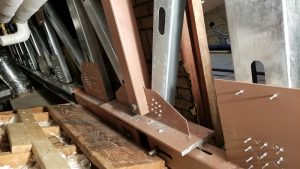
This new truss (“truss J1”) was placed 4 feet from truss J and spanned roughly 5 feet. Typical chords were (2)600S350-68 (placed back-to-back) with webs ranging from 400S250-68 to 600S300-97. Typical panel point connections consisted of #12 screws with 10GA gusset plates (¼-inch-thick Gr. 50 steel at chord splices). The client requested that one panel in the truss be left open to walk through, so some truss chords were HSS6x4x¼ due to moments from a missing web diagonal.
It is common to support existing framing with shore posts, install new members, and then release shoring to shift the load onto new framing. In this case, roof sheathing was essentially being used as a compression flange for the trusses. PE had concerns about reversing member/connection loading that had been in a state of fragile equilibrium by ‘jacking up’ the structure. Therefore, PE designed a pretensioning mechanism to transfer the load into truss J1. A 1-inch-diameter threaded rod was installed on the bottom chord at midspan, and a nut on the rod was tightened with an impact wrench that shortened the bottom chord. This lifted the truss and engaged the roof purlins without the need for jacking. Pretensioning also had the critical benefit of tightening truss connections. By analyzing several upper and lower bounds of stiffness, a pretension force of 18,400 pounds was selected based on the amount of load needed to shift away from truss J while keeping in mind that too much upward movement could damage roofing. FE modeling suggested that this amount of force would result in a maximum net upward movement of 3⁄16 inch at midspan. Though pretension force could be estimated by a “turn-of-the-nut” method, movement/pretension needed to be closely monitored during the operation to avoid damaging the structure. Therefore, PE installed two strain gauges on the threaded rod that were monitored during the pretension process. Torquing was terminated at the desired force, and the pretension mechanism was welded in its final position. Upward movement during pretensioning matched calculated values without damaging the existing structure.
The site and logistic constraints and the structural challenges of a landmark structure required unique and creative solutions. The pretensioned hybrid CFS truss was able to maneuver these constraints while keeping one of Wright’s most famous buildings functional during a major repair.■