
Part 2
In the first installment of this discussion (STRUCTURE, December 2021), I looked at 3 examples of bad habits in contract documents that can cause problems later for fabricators. This month, I offer an additional four examples.
“Just get something on paper!” Beware of reusing details to meet deadlines. Like it or not, your preliminary drawings may get used at some point for pricing and – unfortunately – for fabrication or delegated design. I have questioned fabricators about odd framing, only to find out that there had been several revisions put out by the structural engineer or architect since the set of drawings they last shared with me. One project did not get to what I would call a “complete” set of structural drawings until Addendum #12. A lot changes as drawings develop, but making the drawings look more complete than they really are causes problems as people like me start to base their downstream work on what turns out to be mere eyewash. Saying “We will fix it in the addendum” is like saying you don’t have time to do it right.
Incomplete connection information. Delegated design is not what you do when you have run out of time or budget on a project; it takes a fair bit of documentation to convey everything needed for another engineer to do a complete connection design. If you are delegating connection design to the fabricator, remember that, even as fellow engineers, we are not mind readers. How much information is enough? If you need more information than what you have shown to solve the applicable connection design equations, so will the fabricator’s engineer. Consider the example of transfer forces at braced frames. I see a lot of braced frame elevations with brace forces shown, but very few with transfer forces noted. Yet that is required information for delegated design as listed in the American Institute of Steel Construction’s (AISC) Code of Standard Practice (COSP). It is also information not possible for the connection designer to determine from a typical “envelope” of member forces without being extremely conservative, possibly rendering a connection infeasible. AISC’s excellent Design Guide 29 on vertical bracing connections (in Appendix D) lays out both the need to communicate transfer forces and the difficulties in doing so. Passing design tasks to another engineer requires passing on a lot of information. Consider the time commitment for adequate documentation when deciding how – or whether – to delegate connection design.
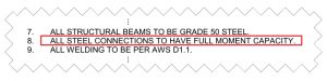
Overly broad details and notes. Specificity takes time but is often essential in communicating your intent. Did the Engineer of Record (EOR) who slapped the note “All steel connections to have full moment capacity” on the drawings (see Figure) really mean all? Even assuming they only meant the actual moment connections, would a short cantilever beam supporting a 2-foot wide strip of floor slab really need to develop the full beam moment capacity? While definitely erring on the side of caution, the best practice is to put the large safety factors into the connections where they are warranted, rather than just by blind application.
There is another way to be overly broad. In the zeal to cover every conceivable variation in typical details, please do not make your details so complex and formula-intensive that only another engineer can interpret them. In fact, if you have complex formulas in your details (and I have seen “details” that looked more like Mathcad® calcs), you should probably dial it back a bit. Under Option 1 for connection design in the AISC COSP, they are unnecessary; under Option 2, even an experienced steel detailer often will not know what to do with all of that “engineerese” (as experienced steel detailers have told me); and, under Option 3, the connection designer should already know how to design the connection. Most contract documents I have received in some way prohibit the fabricator from simply copying the structural drawings to use as their shop drawings; do not do the same with the steel manual or other engineering references.
Misuse of AISC tables. I understand that referencing AISC’s Uniform Design Load (UDL) tables (e.g., Table 3-6) is a simple one-line statement to add to one’s drawings or specs that “covers you,” but does it really? AISC has been discouraging engineers from doing this since at least 1995, but I still see it all the time. However, a capacity table is not a load table. Short beams have the most capacity and (typically) the least load for a given beam size. It does not make sense to require a 50-kip connection capacity for a W10 infill beam that is 4 feet long and has less than 1 kip of actual load while only requiring a 51-kip capacity on a W21 girder with a 50-kip reaction. Besides leading to wild variations in safety factors, the practice can also underspecify beam reactions of composite beams or beams with large loads near the beam end. Hence AISC’s description of it as an “inappropriate” practice. Another example is when a short, shallow beam around a stairwell or elevator core is used in a low-seismic, wind-controlled braced frame. I might suspect there is only a 10-kip beam reaction, at the most, to combine with the vertical component of the brace force, but a 50% UDL directive from the project EOR can easily require me to design that connection for a 40- or 50-kip reaction plus the brace force vertical component, thus eliminating options that are more than adequate and more straightforward to fabricate and erect. Most engineers presented with extreme examples from their drawings readily acknowledge this was not their intent, but let’s break the cycle here and now before it becomes a question on your next project.
We should always be looking for ways to improve our drawings, and next time I will wrap up with three final ways to do that.■