
Engineering projects and building code provisions can often seem like Rorschach tests where two people looking at the same thing can draw sharply different conclusions. This article reviews the two-stage analysis procedure in ASCE 7-16, Minimum Design Loads for Buildings and Other Structures, to consider if the provisions are an innocent inkblot or possibly may be interpreted differently by some.
Engineers simplify what is too complex to solve and what is too complex to solve efficiently in practice. The simplification imposes the obligation to validate that it does not result in a solution that works for the simplified model but is invalid for the complex realities. Because simplification is often an imperfect step away from reality, simplification incurs the obligation of conservatism. The authors’ purpose is to explain how the two-stage analysis simplification can be applied inappropriately to allow for designs that do not provide the level of safety intended by the code. This article also offers remedies to prevent future misuse of this procedure.
A bold and useful simplification in the code’s seismic provisions is the equivalent lateral force (ELF) procedure, predicated on the assumption of approximately equal deformation distribution in one dimension over the structure’s height. But an efficient and ubiquitous building type like podium construction with several stories of light framing perched on one or more levels of concrete (or concrete with concrete masonry) framing is not consistent with the assumptions inherent in the ELF procedure. Using ELF for podium construction can result in mass from the heavier base being applied as inertial loads to the flexible upper portion. Rather than subject podium construction to the rigors and expense of a dynamic analysis, code authors opted for another simplification to keep the ELF procedure on the table for the design of podium construction by adopting the two-stage analysis provisions first introduced in the 1988 Uniform Building Code (UBC).
Conceptually, the two-stage analysis introduces a reasonable simplification to reflect the physical phenomenon of a rigid base not amplifying ground motions to more flexible stories perched above. Further, it appropriately builds in conservatism because analyzing a single building as two separate shorter buildings results in shorter periods for individual building portions, and therefore, equal or greater base shear coefficients for each portion of the structure. However, as demonstrated by the example building described later, this conservatism can be insufficient compensation if the two-stage analysis technique masks the deleterious effects of a base with a torsional irregularity. The two-stage analysis allows the flexible upper portion to be designed as a separate structure fixed at its base using the ELF or modal response spectrum procedure. The reactions from the upper portion are transferred to the rigid base (lower portion), amplified, not reduced, as appropriate for relative seismic response modification factor (R) and redundancy factor (ρ) values. Consistent with the procedure’s imposition of a static force at the top of the rigid base, the lower portion is designed using the ELF procedure.
Code Provisions
The two-stage analysis procedure provisions from ASCE 7-16, Section 12.2.3.2 are listed below:
- The stiffness of the lower portion must be at least 10 times the stiffness of the upper portion.
- The period of the entire structure shall not be greater than 1.1 times the period of the upper portion considered as a separate structure fixed at the base.
- The flexible upper portion shall be designed as a separate structure using the appropriate values of R and ρ.
- The rigid lower portion shall be designed as a separate structure using the appropriate values of R and ρ. The reactions from the upper portion shall be those determined from the analysis of the upper portion amplified by the ratio of the R/ρ of the upper portion over R/ρ of the lower portion. This ratio shall not be less than 1.0.
- The upper portion is analyzed with the equivalent lateral force or modal response spectrum procedure, and the lower portion is analyzed with the equivalent lateral force procedure.
To the main point, these provisions strain the obligation to validate the simplification. Only (a) and (b) provide restrictions to apply the procedure; the other items specify how the procedure is used. While item (a) imposes a relative stiffness requirement, the stiffness parameter is undefined. More importantly, the stiffness obligation does not mandate that the lower portion have properties that provide support equivalent to “fixed at the base.” While item (b) imposes a requirement to compare dynamic properties of the two portions, the period comparison does not ensure the lower portion responds rigidly as the procedure allows the engineer to assume. In the authors’ opinion, although compliance with item (b) is not uniformly adhered to, the provision at least helps diligent practitioners and code enforcement officials keep designs closer to the code intent of a fixed base.
Changes to the two-stage analysis procedure proposed for ASCE 7-22 clarify the application of the ASCE 7-16 provisions but do not result in significant changes to the procedure or the criteria to qualify for its use.
While it is necessary to stipulate quantification of the relative stiffness and period, leaving these as the only criteria to qualify for the simplifying procedure expands eligibility beyond the original intent to simplify the design of podium construction. In this case, the engineering quest to quantify the dynamic nature of the podium obscures the requirement rather than clarifying it.
The loosely defined relative stiffness requirement between the upper and lower portions and the absence of a requirement specifying the lower portion to provide a fixed base to the upper portion throw open the gates for misapplication of the two-stage provisions. The following sections demonstrate some examples of potential misapplications.
Although this article elucidates a flaw in the provisions, a call to action requires the specter of significant consequences – remedied with the analysis of an example building.
Height Limit Loophole
One of the proposed updates for ASCE 7-22 clarifies that the height limits for a given seismic design category (SDC) and building type can be applied as measured from the base of the upper portion. So, if a special reinforced concrete shear wall is being designed in SDC D and is limited to 160 feet per Table 12.2-1, the designer can design a 181-foot-tall building using the two-stage analysis if the bottom 21 feet are at least 10 times as stiff as the upper 160 feet. Based on parametric studies, this is most likely to be the case for a building of similar construction and where the upper portion is more than seven times the height of the lower portion. At that aspect ratio for such a building, the bending flexibility contributes enough to the response to meet the required stiffness ratio. The period of the 181-foot-tall structure would be within the 1.1 limit of item (b) using the approximate period equation of ASCE 7. Note that buildings this tall can usually qualify for both requirements (a) and (b) by virtue of their height, even if the base of the structure is not significantly different than the upper stories.
Torsional Irregularity Loophole
The two-stage analysis provisions do not address the effect that a torsional irregularity in the stiffer lower portion can have on the flexible upper portion. Torsional irregularities are common in podium construction where entry-level architectural features or sloping sites can necessitate an eccentric layout of seismic shear-resisting elements.
A torsional response in the base of the structure results in a rotational acceleration being input into the upper portion. Moreover, if the center of rigidity at the base is eccentric to the center of mass in both horizontal directions, the response in the two horizontal directions will be coupled for both the lower and upper portions. Neither of these effects is captured in a two-stage analysis, where the upper portion is analyzed as a separate structure. Furthermore, ASCE 7-16 applies limitations, penalties, and other requirements to structures with torsional and extreme torsional irregularities, but the two-stage analysis allows the upper portion of a building to potentially avoid these requirements even if it is significantly affected by an extreme torsional irregularity in the base. The code requirements associated with a torsional irregularity include the following:
- A 25% increase in demands for collectors, collector connections, and connections of diaphragms to vertical elements of the seismic force-resisting system for buildings in SDC D through F
- The structure must be analyzed using a 3-D model
- The effects of accidental torsion must be amplified per Section 12.8.4.3
- Structures in SDC D through F exceeding 2 stories must be analyzed using a dynamic analysis
- In addition to the above requirements, an extreme torsional irregularity also requires a 30% increase in the horizontal seismic forces through a redundancy factor, ρ, of 1.3 for buildings in SDC D through F
Example Building
The authors developed a 3-D finite element model of a 13-story concrete shear wall building with a large podium level having an extreme torsional irregularity at the bottom story (Figure 1) to investigate the effects that a torsionally irregular base can have on the upper portion of a building. The example building is set in a location of high seismicity, such as near a significant fault in coastal California classified as SDC D with seismic parameters SDS and SD1 of 1.57g and 0.65g, respectively.
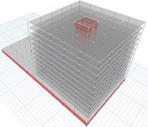
The building has rigid concrete diaphragms (assumed) and four full-height core shear walls at the center of the tower plan area. Relative to the tower, the bottom story has twice the area, a larger unit weight, and two additional perimeter shear walls at two orthogonal building edges. These conditions are typical of a tower and base configuration, plaza construction, and construction on a sloping site.
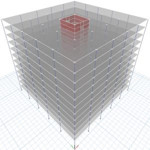
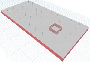
To compare the seismic demands obtained from a single, coupled building analysis to those obtained using the two-stage analysis procedure, the authors also created separate models of the 12-story upper portion and one-story base, as shown in Figures 2 and 3, respectively.
The building qualifies for the two-stage analysis procedure with a base approximately 160 times stiffer than the upper portion and a combined model period 1.1 times that of the upper portion. With accidental torsion effects included, the largest ratio of maximum story drift to average story drift at any level in the upper portion building model is 1.39, giving that model a torsional irregularity per ASCE 7-16, Table 12.3-1, but not an extreme torsional irregularity. On the other hand, the bottom level of the full structure has an extreme torsional irregularity. Because of the torsional irregularities, both the separate upper portion model and the coupled full building model are required to be analyzed using a dynamic analysis per ASCE 7-16, Table 12.6-1, and accidental torsion effects need to be included for both models. Both buildings were analyzed using a Response Spectrum Analysis (RSA) with forces scaled per ASCE 7-16, Section 12.9.1.4, to match the base shear obtained from an ELF analysis. Effects of accidental torsion are captured per Section 12.9.1.5 by modeling a center of mass eccentricity in the dynamic analysis equal to 5% of the diaphragm length.
The shear force in one of the second story core shear walls is examined to compare the response of the upper portion using a two-stage analysis to the response from a combined building model, with the following observations:
- The upper portion building response computed using the two-stage analysis is not affected by horizontal directional coupling (HDC) and has a redundancy factor, ρ, of 1.0.
- The response from the coupled analysis, omitting effects of HDC and ρ, is 23% greater than that obtained from the two-stage analysis. This increases to 34% when adding in HDC effects using the 100-30 combination rule and increases to 74% when also including the ρ of 1.3 required for the coupled analysis.
- Drifts and displacements throughout the structure increased similarly to the shear wall shear demand.
- For this example, ASCE 7-16, Table 12.6-1 requires an RSA for the upper portion due to the torsional irregularity. Performing a two-stage analysis for this building does not significantly affect the effort required to analyze the building.
Discussion
The coupled analysis produced significantly greater responses than the two-stage analysis for this building. Prima facie, the authors accept the coupled analysis as being more reflective of the code intent. If such a building were designed using the two-stage analysis and the framing designed near the code limit states, the limit states would be exceeded based on an analysis of the same building subjected to the coupled analysis. Hence, the building, possibly code-compliant with the two-stage analysis, would not provide the level of safety intended by the code.
Conclusions and Recommendations
The two-stage analysis procedure was developed to simplify the design of light-frame residential buildings on top of one or two-story concrete or masonry podiums. This simplification was needed because a coupled dynamic analysis of this building type has historically been impractical and, due to the significantly heavier base level, a coupled ELF analysis can significantly overestimate the story shears in the upper levels. In most cases, the two-stage analysis procedure produces reasonable, potentially conservative results for this building type. However, the procedure was written in a way that can be applied to almost any building type if the building is tall enough.
The two-stage analysis approach is unnecessary for most structures without light framing as part of the primary lateral load path. This is predicated on the fact that full-building finite-element modeling of these building types is already common practice and is not made significantly more difficult by the presence of a podium. However, this procedure can be used for such buildings to reduce seismic demands from what the code intends.
Buildings with extreme torsional irregularities at their base induce a torsional response in the upper portion of the structure, even if the upper portion of the structure does not have an extreme torsional irregularity. As currently presented in ASCE 7-16 and proposed for ASCE 7-22, the two-stage analysis allows the designer to ignore torsional effects from the base when designing the upper portion of the structure. It also allows the designer to bypass the limitations, penalties, and other requirements associated with this irregularity when designing the upper portion of the structure.
One of the proposed changes to the two-stage analysis procedure for ASCE 7-22 clarifies how height limits are to be interpreted for the procedure but also opens the door for misuse of the procedure to increase height limits for certain building types.
The authors recommend modifying the provisions for the two-stage analysis procedure to accomplish the following:
- Limit the procedure so that it can only be applied to light-frame structures over concrete or masonry bases.
- Impose a maximum period on the base model with the mass of the upper portion lumped at the top of the lower portion. The period should be short enough to approximate a rigid dynamic response and should not be a relative requirement based on the period of the upper portion.
- Require the designer to account for the effects of torsional response in the base when designing the upper portion of the structure, including rotational accelerations, horizontal response coupling, and other code requirements associated with torsional and extreme torsional irregularities.
- If the recommendation to limit the procedure to light frame upper portions is not implemented, require the height limits of Table 12.2-1 to be measured to the base of the full structure rather than the base of the upper portion.
- Revise the code commentary to express the intent of a two-stage analysis.
Closing
The building code is a minimum standard for safety and should not leave room for interpretations that fail to achieve the code-intended level of safety. Hoping that conventional interpretations, or what some would consider reasonable judgment, covers engineering flaws in the code is professional abdication. Or, returning to the Rorschach analogy, why would we create an inkblot that one person could interpret vastly different than another?■
References
ASCE, 2016, Minimum Design Loads and Associated Criteria for Buildings and Other Structures, ASCE 7-16, American Society of Civil Engineers, Reston, VA.
ASCE, 2021, Proposed Changes to Minimum Design Loads and Associated Criteria for Buildings and Other Structures, ASCE 7-22, American Society of Civil Engineers, Reston, VA.
International Conference of Building Officials, 1988, Uniform Building Code, Whittier, CA.