
Part 1: Loads (Chapter 16)
This five-part series discusses significant structural changes to the 2021 International Building Code (IBC) by the International Code Council (ICC). Part 1 includes an overview of changes to Chapter 16 on loads. Only a portion of the total number of code changes to this chapter are discussed in this article. More information on the code changes discussed here can be found in the 2021 Significant Changes to the International Building Code, available from ICC.
IBC Chapter 16 establishes minimum design requirements so that the structural components of buildings are proportioned to resist the loads that are likely to be encountered. In addition, this chapter assigns buildings and structures to risk categories that are indicative of their intended use. The following modifications were approved for the 2021 IBC. Changes are shown in strikethrough/underline format with a brief description of the change’s significance.
Construction Document Wind Zones
Component and cladding wind zones must now be identified in the construction documents.
1603.1.4 Wind design data. The following information related to wind loads shall be shown, regardless of whether wind loads govern the design of the lateral force-resisting system of the structure:
No changes to items 1-4.
5. Design wind pressures and their applicable zones with dimensions to be used for exterior component and cladding materials not specifically designed by the registered design professional responsible for the design of the structure, psf.
Change Significance: There has been some confusion about how the 2016 edition of ASCE 7, Minimum Design Loads and Associated Criteria for Buildings and Other Structures, component and cladding (C&C) wind pressure zones are to be applied – specifically what dimensions are prescribed for various building zones. A description of C&C wind pressure zones in the construction documents is intended to show correctly applied requirements for roof and wall assemblies and their coverings.
Risk Categories of Assembly Spaces
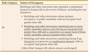
Mixed occupancy buildings with assembly spaces are now designated as Risk Category III when the total public assembly occupant load exceeds 2,500 people.
Change Significance: Group R-1 hotels often have convention center facilities with multiple large ballrooms and other assembly spaces, but public assembly is not the primary occupancy of the building. These buildings have historically been classified as Risk Category II. Conversely, smaller buildings, such as theaters, consist of one or more spaces where the primary occupancy is public assembly with a cumulative occupant load of over 300 that must be designed to the higher Risk Category III requirements. However, the total occupant load is much smaller when compared to a Group R-1 hotel.
Table 1604.5 includes a new condition under Risk Category III for buildings with multiple occupancies, containing assembly spaces with an occupant load greater than 300 each, while also having a cumulative occupant load for the 300-plus-occupant assembly spaces of more than 2,500. Buildings that meet these criteria are now assigned to Risk Category III rather than Risk Category II. The new threshold requires the existence of the two conditions previously stated to establish a Risk Category III classification.
An additional revision addresses daycare facilities classified as Group I-4 occupancies. Consistent with the application for a Group E occupancy in a mixed occupancy building, a building used for daycare purposes is considered Risk Category III when the total occupant load for the Group I-4 occupancy, or combination of Group E and Group I-4 occupancies, exceeds 250.
Load Combinations
The strength design and allowable stress design load combinations have been deleted, while direct reference to Chapter 2 of ASCE 7 has been added to Section 1605.
1605.1 General. Buildings and other structures and portions thereof shall be designed to resist the Strength Load Combinations specified in ASCE 7 Section 2.3, the Allowable Stress Design Load Combinations specified in ASCE 7 Section 2.4, or the Alternative Allowable Stress Design Load Combinations of Section 1605.2.
Exceptions:
-
- The modifications to Load Combinations of ASCE 7 Section 2.3, ASCE 7 Section 2.4, and Section 1605.2 specified in ASCE 7 Chapter 18 and 19 shall apply.
- When the Allowable Stress Design Load Combinations of ASCE 7 Section 2.4 are used, flat roof snow loads of 30 psf and roof live loads of 30 psf or less need not be combined with seismic load. Where flat roof snow loads exceed 30 psf, 20 percent shall be combined with seismic loads.
- Where the Allowable Stress Design Load Combinations of ASCE 7 Section 2.4 are used, crane hook loads need not be combined with roof live loads or with more than three-fourths of the snow load or one-half of the wind loads.
1605.3.2 1605.2 Alternative basic allowable stress design load combinations. In lieu of the Load Combinations in ASCE 7 Section 2.4, structures and portions thereof shall be permitted to be designed for the most critical effects resulting from the following combinations… [unchanged text omitted for brevity] Where required by ASCE 7 Chapters 12, 13, and 15, the Load Combinations including overstrength of ASCE 7 Sections 2.3.6 shall be used.
D + L + (Lr or S or R) (Equation 16-17 16-1)
D + L + 0.6ωW D + L + 0.6W (Equation 16-18 16-2)
D + L + 0.6ωW + S/2 D + L + 0.6W + S/2 (Equation 16-19 16-3)
D + L + S + 0.6ωW/2 D + L + S + 0.6W/2 (Equation 16-20 16-4)
D + L + S + E/1.4 (Equation 16-21 16-5)
0.9D + E/1.4 (Equation 16-22 16-6)
Unchanged exceptions and additional deleted text not shown for brevity and clarity.
Change Significance: Strength load combinations and basic allowable stress design (ASD) load combinations are replicated directly from ASCE 7. Deletion of the IBC load combinations removes minor variations in the requirements between the IBC and ASCE 7 by eliminating duplication of the equations.
The third set of load combinations are from legacy codes that predate the IBC. In previous editions, the alternative ASD load combinations permitted the use of a 1/3 increase in allowable stresses when evaluating load combinations containing short-term transient loads caused by winds. The basic allowable stress combinations did not permit the reduction in loads but applied a factor of 0.75 to transient loads, including live, snow, wind, and seismic loads, when more than one of these loads was considered simultaneously.
The omega factor, ω, has been deleted from the alternative ASD load combinations to limit misuse of the stress increase, thus increasing the load due in part to wind forces.
Dead Loads
Dead loads at the roof level have been clarified, as well as fixed service equipment concentrated loads.
1606.2 Design dead load. Weights of materials of construction. For purposes of design, the actual weights of materials of construction and fixed service equipment shall be used. In the absence of definite information, values used shall be subject to the approval of the building official.
1606.3 Weight of fixed service equipment. In determining dead loads for purposes of design, the weight of fixed service equipment, including the maximum weight of the contents of fixed service equipment, shall be included. The components of fixed service equipment that are variable, such as liquid contents and movable trays, shall not be used to counteract forces causing overturning, sliding, and uplift conditions in accordance with Section 1.3.6 of ASCE 7.
Exceptions:
-
- Where force effects are the result of the presence of the variable components, the components are permitted to be used to counter those load effects. In such cases, the structure shall be designed for force effects with the variable components present and with them absent.
- For the calculation of seismic force effects, the components of fixed service equipment that are variable, such as liquid contents and movable trays, need not exceed those expected during normal operation.
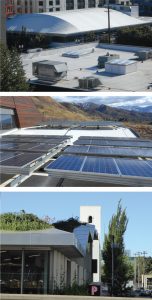
1606.3 Photovoltaic panel systems. The weight of photovoltaic panel systems, their support system, and ballast shall be considered as dead load.
1606.3 Vegetative and landscaped roofs. The weight of all landscaping and hardscaping materials for vegetative and landscaped roofs shall be considered as dead load. The weight shall be computed considering both fully saturated soil and drainage layer materials and fully dry soil and drainage layer materials to determine the most severe load effects on the structure.
Change Significance: The weights of vegetative roofs, solar panels, and fixed service equipment have been clarified to provide consistency between the IBC and ASCE 7 (Figure 1). The weight of fixed service equipment includes both the equipment’s empty weight and the maximum weight of the contents. For example, the weight of liquids is to be included in the dead load of piping and tanks, and the weight of conduit and wiring is to be included in the dead load of cable trays. In addition, as content weight may be variable, it cannot be assumed to counteract the effects of overturning, sliding, and uplift forces. Exceptions in IBC Section 1606 specifically address the calculation of variable loads for liquids and moveable equipment.
Snow Maps
The IBC ground snow load map has been updated to provide consistency with ASCE 7-16 by referencing ASCE 7 snow load tables for states with large case study areas (Figure 2).
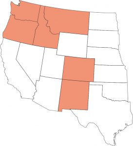
Change Significance: Updating Section 1608 harmonizes snow load provisions with ASCE 7-16. ASCE 7 has a ground snow map that references new ground-snow load tables; these include tables for seven states: Colorado (7.2-2), Idaho (7.2-3), Montana (7.2-4), Washington (7.2-5), New Mexico (7.2-6), Oregon (7.2-7), and New Hampshire (7.2-8). The state tables list ground snow loads and maximum elevations for major cities and towns in each region of a given state. IBC Figure 1608.2 indicates which states have supplemental data within the ASCE 7 standard.
Soil-Caused Uplift
Hydrostatic and expansive soil uplift pressures are now addressed in Section 1610 on soil loads.
1610.2 Uplift loads on floor and foundations. Basement floors, slabs on ground, foundations, and similar approximately horizontal elements below grade shall be designed to resist uplift loads where applicable. The upward pressure of water shall be taken as the full hydrostatic pressure applied over the entire area. The hydrostatic load shall be measured from the underside of the element being evaluated. The design for upward loads caused by expansive soils shall comply with Section 1808.6.
Change Significance: Section 1610 has not previously addressed uplift loads from hydrostatic pressure or expansive soils. Requirements addressing uplift forces are now to be applied when appropriate and included in the design. The hydrostatic pressure provisions include a required determination of loads based on measuring to the underside of construction per ASCE 7 Section 3.2.2. While this is a straightforward provision of fluid mechanics, the new provisions are intended to prevent the use of common elevations shown on construction drawings, such as floor elevations or the top of foundation construction, as the elevation at which to apply hydrostatic forces. Instead, the new language explicitly states that hydrostatic pressures should be applied to the underside of a foundations’ lowest horizontal element.
A pointer has been added to Section 1808.6, Design for Expansive Soils, to help in determining the minimum required uplift due to movement of soils below a building when expansive soils are present.
Rain Loads
Secondary drainage system rain loads have been updated to be consistent with ASCE 7.
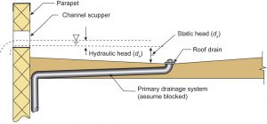
1611.1 Design rain loads. Each portion of a roof shall be designed to sustain the load of rainwater that will accumulate on it if the primary drainage system for that portion is blocked plus the uniform load caused by water that rises above the inlet of the secondary drainage system at its design flow as per the requirements of Chapter 8 of ASCE 7. The design rainfall shall be based on the 100-year hourly rainfall rate indicated in Figure 1611.1 15-minute duration event or on other rainfall rates determined from approved local weather data. Alternatively, a design rainfall of twice the 100-year hourly rainfall rate indicated in Figure 1611.1 shall be permitted.
[Equation unchanged]
1611.2 Ponding instability. Susceptible bays of roofs shall be evaluated for ponding instability in accordance with Section 8.4 Chapters 7 and 8 of ASCE 7.
Change Significance: Secondary (overflow) system design has been harmonized with roof rain load provisions to provide realistic expectations of the roof drainage system and potential roof loading by rainfall (Figure 3). The IBC is now consistent with ASCE 7 provisions. Calculations for the design mean recurrence interval and duration for determining the hydraulic head are available in both ASCE 7 and the IBC.
Note that the use of twice the 60-minute duration is close to the 15-minute duration rainfall rate. Also, note that the 2021 IBC rainfall map (Figure 1611.1) provides a 60-minute duration rather than the 15-minute storm duration. However, the 2021 IBC, by giving two options – the 15-minute duration or twice the 60-minute duration – results in values comparable to ASCE 7. Note that the 2021 International Plumbing Code has not yet been updated to reflect the 100-year/15-minute (or twice the 100-year hourly) duration rainfall event design requirement for secondary drainage systems; the structural engineer would be advised to coordinate with the plumbing engineer to assure that the secondary drainage systems are designed for the higher rainfall rate.
One source for rainfall data is the National Oceanic and Atmospheric Administration (NOAA) National Weather Service Precipitation Frequency Data Server–Hydrometeorological Design Studies Center (https://bit.ly/3lu1PpS) for precipitation intensity (inches per hour) based on the 100-year mean recurrence interval. HDSC’s data lists both 15-minute and 60-minute duration data.
Conclusion
Structural engineers should be aware of significant structural changes that have occurred in the 2021 IBC. Many of the new code provisions harmonize the IBC and ASCE 7. Component and cladding wind zones must now be identified in the construction documents. Mixed occupancy buildings with assembly spaces are now designated as Risk Category III when the cumulative occupant load for the 300-plus-occupant assembly spaces exceeds 2,500 people. The strength design and allowable stress design load combinations have been deleted while direct reference to Chapter 2 of ASCE 7 has been added.
Dead loads at the roof level have been clarified, as well as fixed service equipment concentrated loads. The IBC ground snow load map has been updated to provide consistency with ASCE 7-16 by referencing ASCE 7 snow load tables for states with large case study areas. Hydrostatic and expansive soil uplift pressures are now addressed. Secondary drainage system rain loads have been updated to be consistent with ASCE 7.
To download published errata for the 2021 IBC, including Table 1604.5, go to iccsafe.org/errata-central.■
An upcoming issue will include an article specifically devoted to rain load calculations with design examples comparing 2021 IBC to 2018 IBC provisions.