
The Transportation Center at Pima Community College’s Center of Excellence for Applied Technology is 43,000 square feet with a total of 27 work bays, including spaces for testing and diagnosis of electric vehicles, faculty offices, classrooms, a dynamometer room, equipment storage, and a large public entry. The unique utility of the building governed its placement, such as the clearance necessary for cars to drive around the lobby and into the work bays. In addition, the structural design focuses on responding to flexibility and visibility, resulting in a state-of-the-art, hands-on learning environment reflected in the vast amount of exposed steel. A high degree of coordination and unique framing concepts, which the team termed “structural gymnastics,” led to the project’s success. DLR Group provided planning, architecture, structural engineering, electrical engineering, interiors, and construction administration services for the Transportation Center.
Design Creativity
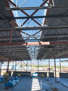
The structural system’s creative design focused on flexibility and visibility, revealed in the exposed steel. Allowing daylight into the building was identified as a critical characteristic of the project early in the design. In response, a spectacular 8.5-foot-wide skylight illuminates the high-volume work bay. Creativity in structural design responded to maintaining continuity in load transfer, reflected by the unique stitched-together design at the high bay roof where the diaphragm was made discontinuous by the skylight. Finite element analysis using RAM Structural System was performed using semi-rigid diaphragms and analyzing the “stitching” as a horizontal truss.
Transitioning from the ample auto bay space to the administration wing required transferring both the gravity and lateral loads through a non-orthogonal structural grid. The transition was accomplished through a series of transfer girders and custom drag connections. The lateral load transfer at the interface of the high-volume work bay space and the adjacent two-story classroom building presented a unique challenge. The two-story classroom box is essentially skewed and overlapped into the high-volume work bay space. The lateral force-resisting systems were reimagined to ensure the flexibility of the rooms at the interface of these two different spaces. The solution resulted in a custom transfer girder connection to migrate the load from the classroom roof through a wide-flange girder rotated onto its weak axis and dragged to the high-volume work bay braced frames.
Additionally, to create a light and airy shade structure, the large entry canopy was designed to tie into the lateral system of the main building, which eliminated the need for additional bracing. This was achieved with custom drag connections in each direction between the two structures.
Complex Criteria
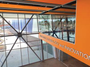
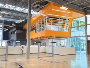
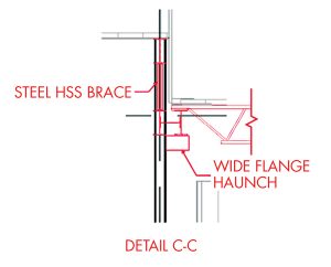
Unique problems arose from the angular layout of the building, horizontally and vertically, that created framing challenges and required extensive detailing. The complex geometry involved a high degree of modeling and coordination for stud soffit supports, exterior wall supports, skylight framing, and high/low roof framing. At an imposing 80-degree slope, the complex and unique canted brace highlights the slanted entry wall. The brace required an intricate degree of analysis due to the increased eccentricity. The 80-degree slope continues into the glass conference room that overlooks the Autolab and lobby. The large corner conference room with a floating effect is another design element that was crucial to the overall design of the building. The placement of columns and the addition of large transfer girders were crucial to delivering the intended visual impact.
The tall exterior walls at the high-volume space exceeded 50 feet plus 11-foot cantilevered parapets. These walls required a secondary framing system connected to the main steel frame system and increased the in-plane loading into the roof diaphragm and lateral system. In addition, the wide flange wind girts were orientated with the strong axis horizontally to provide greater strength and deflection control to resist out-of-plane forces while also being in line with the primary structural framing.
Innovative Use of Materials
Innovation was seen in the application of the exterior panel façade system, resulting in a more cost-effective, lightweight, and easy to install solution. Integrating this system into the structural design involved challenges such as providing custom gravity supports and coordinating the lateral supports for the wall system with the main lateral resisting system – all of which are coplanar. The perimeter structure required a secondary analysis for out-of-plane lateral forces in conjunction with gravity and in-plane lateral forces to support the exterior wall system.
The exterior translucent panel system was selected for its best-in-industry thermal performance and light transmission. The panels reduce solar heat gain, which drastically reduces the heating and cooling loads of the building. The diffused light transmission through the panels reduced lighting needs and provided electrical savings. Because the panels are prefabricated and lightweight, savings were also provided on transportation and installation time, approximately 2/3 less than a standard wall system. Structural cold-formed metal framing detailing at the exterior wall system allowed for elevated gravity support, material changes between translucent and insulated panels, and accommodated differential movement at the roof.
Design Efficiency
Ingenuity of design for efficiency was at the forefront of the design process from the beginning. Developing specific detailing in the Schematic Design stage minimized late and costly design changes later, which would have impeded the project’s success. Many design complexities required custom solutions, resolved through a high level of coordination and modeling to ensure the structural system was integrated with all other building systems.
The transfer girder and steel framing plans were detailed early in the process to ensure smooth coordination and best-in-class design. The exterior façade and structural systems were selected and designed to provide long-term durability and speedy construction sequencing. The CMU walls at the bottom of the exterior walls provided a durable base necessary for the automotive work environment. The structural steel and paneled wall system above enabled quick installation while providing the sought-after thermal and lighting benefits during the life of the building.
Constructability
Challenges related to constructability were solved using a high degree of coordination and validation in framing to ensure that the structural systems worked within the angular layouts of the building. The structural system had to allow for the movement of vehicles through the space, which meant coordination of column locations, providing cantilevered floor systems, and providing moment frames to guarantee open access. The atypical requirements of the automotive equipment meant making sure these systems were accounted for early in design to avoid conflicts during construction.
The foundations in the Autolab were coordinated to prevent clashes with under-slab exhaust systems and integrated mechanical systems. Moreover, most mechanical units were installed on the roof of the large auto bay space, and ducts then serviced the lower volume classroom spaces. To access the classroom spaces, however, the ducts had to squeeze through the large transfer girders at the interface of the two spaces, leaving little to no room for error. The team used Navisworks clash detection to identify structural and mechanical issues before they happened in the field to aid in coordination and field challenges when installing mechanical systems.
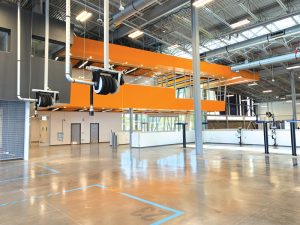
Hose reels that hung from high bay roof structure required custom detailing and an understanding of construction sequencing. In a standard automotive service area, hose reels are hung from the ceiling, typically only 12 feet in height. With a roof that went as high as 50 feet, steel framing had to cantilever down while still meeting equipment deflection limits and providing adequate clearance below.
The overall result of the Transportation Center is a bright, open space that is highly functional to its occupants. The seamless transition into different spaces with geometric peculiarities is a true testament to the team’s early vision and high degree of coordination.■
Project Team
Owner: Pima Community College
Structural Engineer and Architect: DLR Group
Contractor: Chasse Building Team
Structural Software: RAM Structural Systems, RAM Connection, RAM Elements, RAM SBeam, Enercalc, Navisworks