
Engineers routinely need to analyze and design indeterminate structures. Today they would use any one of several analytical software packages commonly loaded on their computers. The programs are so powerful that it does not take long to develop the input and perform the analysis, even for a major building. Sifting through the output and finding the desired answers might be the greatest effort involved.
However, before the regular use of computers (sorry for the history lesson, but it was not that long ago), the analysis method of choice was the moment distribution method, developed in the 1930s by Professor Hardy Cross of the University of Illinois. Besides being a clever analytical concept, it has an inherent simplicity and physical logic that is easy to grasp. It works like this for analyzing a structure with continuous beams with multiple supports: 1) every beam-column joint in the structure is assumed to be fixed from rotation and appropriate fixed-end bending moments are applied to the joints, and 2) then each fixed joint is released sequentially, and the fixed-end moments, which at the time of the first joint release are not in equilibrium, are distributed to adjacent members. The process of fixing, releasing, and re-distributing bending moments is repeated many times until an equilibrium is reached or until the engineer decides that the amount of undistributed moment is small enough to ignore.
Whether the engineer is working today or in the past, getting the right answer, or better yet, a “precise” answer (since there is never a “right answer”) to the problem, may involve more effort than the engineer wants to exert or has the time or budget to spend. Often, an approximate answer to an indeterminate problem is good enough. Engineers appreciate that, with ever smaller powerful handheld computers, the “right answer” is never that far away. However, there are many times when calculating an approximate answer, while at a job site, on the way home from work, or away from the office, is something an engineer needs to do because that is all that is really needed at the time.
As is discussed later, these approximate analytical techniques are the foundations of structural engineering. Of course, today’s engineers can consider loading conditions that prior generations knew about but lacked the tools (or the computational desire) to evaluate. They can also study the post-elastic response of a structure subjected to a suite of actual earthquake ground motions, with the computer churning away while they take a long lunch.
When it comes to hiring entry-level engineering staff, many employers look for candidates having the very advanced knowledge discussed above. But more importantly, they want engineers with solid educational backgrounds who have the ability to think on their feet and quickly assess and solve problems without needing to perform a computer analysis, which, as is commonly known, is just an approximation. Being able to cut through the clutter and get an answer that is in the “ballpark” is highly valued by employers but hard to teach. To underscore the point, how many times has an engineer gotten a confusing answer from a computer model and then needed to go back to first principles to figure out what was wrong and how to fix it? Like troubleshooting a finicky automobile, an engineer needs to assess what is working and what is not using handy and trustworthy tools.
This article discusses four different indeterminate structures that are encountered regularly in engineering practice and that firms also use in their entry-level employee interviews, namely:
- Lateral analysis of a one-story, one-bay frames.
- Gravity analysis of a one-story, two-bay frame with a pinned base.
- Lateral analysis of a one-story, two-bay frame with a fixed base.
- Lateral analysis of a multi-bay, multi-story, slender high-rise frame.
It would be fair to say that many older, experienced engineers believe that solving these issues quickly and approximately is part and parcel of being an engineer and would wonder why an interviewer would ask an applicant engineer about these situations. But for those not involved in hiring, it would be surprising to know how many engineers, many educated at our most prestigious universities, have trouble with these concepts, even after accounting for some degree of nervousness and the pressure of a job interview. Maybe these concepts are not taught anymore, or the amount of time allotted to teaching them is too short. In either case, this does a disservice to our engineering graduates. Most firms have the capacity to train engineers in more advanced analytical and design techniques. However, if the new hire’s foundation in statics and mechanics is lacking or weak, more advanced tasks are more difficult to learn.
Analyzing the Indeterminate Structure
Solving statically determinate structures is straightforward because basic statics can be employed, namely the summing of forces in the x and y directions (for 2-D systems) and the summing of rotational moments (caused by the applied forces) about a point. Solving statically indeterminate structures is mainly the task of turning the indeterminate structure into a determinate structure. This is done by making simplifying assumptions about the location of inflection points (also known as points of counter-flexure) in structural elements that are bending under load (either due to gravity or lateral loads) and judging whether structures subjected to lateral loads resist loads primarily from a lateral shearing action or primarily from a lateral bending response. Once this is done, the rest is just math.
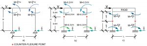
Lateral Analysis of One-Story, One-Bay Frames
There are three variations of this simple structure: a) a pinned base with beam and columns of approximately equal stiffness, b) a fixed base with beam and columns of approximately equal stiffness, and c) a fixed base with a rigid beam and two flexible columns of approximately equal stiffness. Assume there is a lateral load applied at the beam level, there is no gravity load, the members have infinite axial stiffness, the shear in the columns is equal, and the members have no mass.
For all three conditions, the first step is to identify the counter-flexure points in the beams and columns. Start this process by drawing the deflected shape for each structure. Going back to the job interview process, many applicants have difficulty with the rotation of the beam-column joint and the curvatures of the beam and column at the joint. Rather than applying the forces to determine the moment and rotation, they guess and get it all backward. However once the curvatures are drawn correctly, the counter-flexure points can be located. This creates a determinate structure, and the shears and bending moments in the beams and columns can then be determined. The pinned-base structure produces the largest bending loads because the base (say the ground) helps the least. The fixed-base, rigid-beam structure has equal top and bottom bending moments and the least column bending. The fixed-base, flexible-beam structure falls somewhere in the middle. The inflection points in the columns are near (or slightly above) mid-height, creating the potential for slightly higher bending moments in the columns than that for the fixed-fixed structure, depending on the relative stiffnesses of the beams and columns. Since the analysis is approximate, it is also acceptable to assume the inflection point is at mid-height.
One might wonder – why spend so much time on such a simple structure? The answer is that these are the potential conditions for the first story columns in many kinds of buildings: a structure without a basement or any base rigidity, a structure with a basement and “normal” second-floor framing, and a structure with a basement and very rigid beams at the second floor. The required sizes of the columns, and the beams but to a lesser extent, can vary greatly.
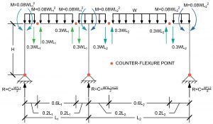
Gravity Analysis of a One-Story, Two-Bay Frame with a Pinned Base
The structure is a one-story, two-bay frame with unequal beam spans. Assume there is gravity load applied at the beam level, there is no lateral load, the members have infinite axial stiffnesses, and the members have no mass.
It would take a long time to analyze this structure with hand calculations, and it would take a fair amount of time (allowing for a few modeling errors), even with a computer. As with a one-bay frame, the first step is to identify the counter-flexure points in the beams. Start this process by drawing the deflected shape of the beams. Once the beam curvatures are drawn, the counter-flexure points can be located. The beam design aids in the American Society of Steel Construction’s (AISC) Steel Construction Manual show the inflection points for fixed-fixed beams. The inflection points near the center column are more similar to the fixed-fixed condition. Since the exterior beam-column joints rotate to some extent, the inflection points are closer to the columns. The columns do not have inflection points due to the pinned base condition. One should exercise some judgment here, remembering this is an approximate analysis. Adding the inflection points creates a determinate structure, and the shears and bending moments in the beams and the shears, bending moments, and axial loads in the columns can then be determined.
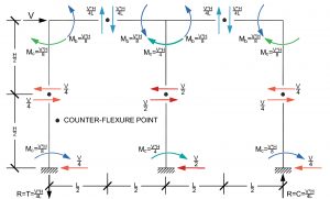
Lateral Analysis of a One-Story, Two-Bay Frame with a Fixed Base
A variation of the previous structure is a one-story, two-bay frame with equal beam spans with only lateral loads due to earthquake loads at the floor level. As with the one-bay frame, assume there is no gravity load applied at the beam level, the members have infinite axial stiffnesses, and the members have no mass.
The interior beam-column joint is roughly twice as stiff rotationally as the exterior joints (two beams compared to one beam), so assume that the interior column resists twice as much shear as the exterior columns. This is the basic assumption in the portal frame method.
As with the other structures discussed above, the next step is to identify the counter-flexure points in the beams and columns. Start this process by drawing the deflected shape of the structure using the same logic as for the one-bay frames. Assume the inflection points are at mid-length of the beams and mid-height of the columns. This sets the counter-flexure points. This creates a determinate structure, and the shears and bending moments in the beams and the shears, bending moments, and axial loads in the columns can then be determined. A fixed-base structure replicates a building with a basement where the columns extend downward to the basement floor level or a building without a basement but with a rigid grade beam system near the surface grade intended to provide column base fixity. A pinned base would replicate a building without a basement or one with a minimal flexible grade beam system.
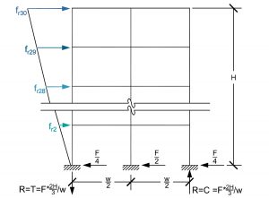
Lateral Analysis of a Multi-Bay, Multi-Story, Slender High-Rise Frame
For the last structure, a tall, slender building of indeterminate height is examined. The height does not really matter so long as the building is considerably taller than it is wide. The predominant response to lateral loading is flexural bending of the tower as opposed to shearing action.
Assume lateral loads due to earthquakes are applied at each floor level in a triangular shape with the centroid at ⅔ of the height, H; there is no gravity load applied at the beam levels; the beams have infinite axial rigidity; the columns have equal axial stiffnesses; and, the members have no mass.
Rather than identifying the counter-flexure points in the beams and columns as with the other structures whose response is predominately a shearing action, assume the tower bends like a cantilevered pole extending from the ground. Due to the lateral loads only, the columns on one face of the tower are in tension, and the columns on the other face are in compression. For the example building with three columns, sum the moments about the center column (the neutral axis) and determine the axial column’s loads. This simplification is the essence of the cantilever method. Statics dictate that the center column gets no axial load from the lateral load condition. Suppose the structure has more columns, assuming that plane sections remain plane in bending. In that case, the columns will sustain axial loads proportional to their distance from the neutral axis at the centerline of the building.
If the inflection points are assumed at the mid-lengths of the beams and mid-heights of the columns, the beam and column bending moments and shears can then be determined. Tall buildings have large column axial loads; it would be fair to simply add those to the column’s loads already determined based on tributary area.
Conclusion
The ability to determine approximate answers to complicated problems is handy in the real world of engineering. Engineers will be amazed at how much respect they earn when they can provide a contractor with a quick answer in the field without having to go back to the office to figure it out, or when they can, in just a few minutes, help another engineer troubleshoot a computer model that has been frustrating them for several hours. The basics never go out of style and are reliable tools if learned early and well.■