
Building taller, longer, stronger, and faster is one of humanity’s eternal aspirations. It is not by chance that the construction industry measures achievements by comparing the height of skyscrapers, the size of arenas, and the span of bridges.
Currently, seven bridges exceed 4,921 feet (1,500 m) in span. The Akashi-Kaikyo Bridge, Japan (1998) has the longest span at 6,532 feet (1,991 m). The Çanakkale Strait Bridge in Turkey, to be completed in 2022, will surpass this with a record-breaking 6,637 feet (2,023 m) span.
There were projects for longer bridge spans over the English Chanel, the Gibraltar Strait, and the Messina Strait, where construction preparatory work started in 2009, only to be abandoned in 2013. As a result, the longest bridge span has not increased for 23 years. When considering long bridge spans, engineers choose between suspension and cable-stayed bridges, the only systems to achieve spans over 3,281 feet (1,000 m) (the longest span by any other system being an 1,811-foot arch (552-m)).
Like all bridge systems, suspension and cable-stayed structures are continuously enhanced based on the development of high-strength materials, newer construction technologies, quality control, and maintenance. However, it is no longer sufficient to simply increase the structural members’ sections to provide longer spans. We are at the point where it may be necessary to implement new or at least modified structural systems.
Hybrid Suspension Systems
One option for increasing the length of long-spans is using hybrids of suspension and cable-stayed bridge systems, or hybrid suspension. The idea is to reduce the suspension span while maintaining the required clear span length. In hybrid suspension, this is achieved by adding “on-deck interior” cable-stayed pylons at 1,000-1,600 feet (300-500 m) from the supports, combining cable-stayed cantilevers (extending from the towers) and a central suspension portion. This approach reduces the suspension length, related cable forces, and the demand on the structure, so a free span of 11,811 feet (3,600 m) can be obtained using a suspension structure of about 8,202 feet (2,500 m).
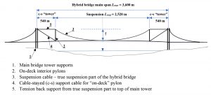
Depending on the span’s requirements, the system may include one central “main” span plus two side spans or a combination of multiple “main” spans with two side spans. The towers are structural systems with cable-stayed supported cantilevers extending on each side or at least extending into the main span (Figure 1). These cantilevers support the “on-deck pylons” and the central suspension portion. The forces at both ends of the pylons are transferred with tension cables to the top of the central tower. The pylons’ vertical reactions are transferred with diagonal cables to the top of the main towers; the horizontal tension forces from the central suspension cables are also transferred to the top of the main towers, but with horizontal cables (Figure 1). The main cables support the deck-girder in the suspension portion with regular suspenders. In contrast, between the on-deck pylons and the towers, the deck-girder is supported with cable-stays directly by the towers.
This approach has potential that needs to be verified for feasibility and economy. The basic idea for reducing the suspension span is not new. The idea was explored by Joseph Strauss in the early design of the Golden Gate Bridge (1932), with colossal steel truss cantilevers from the towers shortening the main suspension span. Sergio Musmeci used a different method for a Messina Strait bridge competition (1970) with Lclear = 10,827 feet (3,300 m), and T.Y. Lin for a Gibraltar Strait bridge feasibility study (1990) with several 16,404-foot spans (5,000-m). The author also considered the prospect of a hybrid suspension system for a Messina Strait bridge feasibility study (1988) with Lclear = 9,350 feet (2,850 m).
In principle, shortening the suspension length should result in substantial savings. The reduction of the suspension cable forces from a classic suspension system with Lmax span to a shorter suspended portion Lsusp of a hybrid system, keeping the same free main spans Lmax , is proportional to the square of the ratio of the lengths of the two systems (Lsusp/ Lmax )2, if the sag to span ratio (f/L) for both systems is kept the same. For example, the reduction of the main cable horizontal force (and all other related forces) resulting from transforming an 11,811-foot classic suspension (3,600-m) to hybrid suspension with an 8,268-foot suspension portion (2,520-m) is (8268/11811)2 = 0.49, a reduction by about half, with all consequent advantages and savings.
Which system is more efficient – classic suspension or hybrid suspension? Is the hybrid system more efficient as a whole than a classic suspension bridge with the same main span? While the main cable forces are significantly reduced in the hybrid system, there is no change in the total vertical reactions at the towers and foundations, which remain the same regardless of the reduced suspension span. The hybrid system reduces the length of the suspension. It adds new elements like “on-deck pylons” and diagonal main cable stays. Pylon reactions are transferred to the main supports, and compression is imposed on the deck-girder system between the “on-deck pylons” supports and the main towers. Some of the gain from shortening the suspension span is offset by these transformations of the system.
Hybrid versus Classic Suspension Systems Feasibility Study
The efficiency of suspension bridges depends mostly on the main cable sag. Deeper sags reduce the cable force but require taller towers. Classic suspension options have sags, f, ranging from 1/7 to 1/12 of the span, Lmax . While bridges with deeper sag ratios (from 1/7 to 1/9 of Lmax ) are more efficient than those with smaller sag ratios (from 1/10 to1/12 of Lmax ), deeper sags require much taller main towers than smaller sags. The heights of the towers are determined as the sum of the initial sag, plus 3% longitudinal deck slope (from center to towers), 33-foot allowance (10-m) for the deck structure, plus 213 feet (65 m) of minimum clearance above water. The longitudinal slope is required to remain at least 1% after considering the elastic deformation under maximum load q. The tower heights for an 11,811-foot suspension span (3600-m) with ratios between 1/7 and 1/9 are 2,037 to 1,663 feet (621 to 507 m), while for ratios from 1/10 to1/12, they are 1,532 to 1,335 feet (467 to 407 m). For practical reasons, engineers have used sags of around 1/9 of L for most of the recent longest bridge spans to optimize balance between the overall efficiency and constructability of the towers.
A simple approach to calculate the total structural quantity for comparing the efficiency of different hybrid options is to calculate the sum of the products of element forces times element lengths. The smaller the sum, the more efficient the system. The element forces and support reactions are functions of q, the total vertical uniform dead + live load per linear meter. The total structural quantity includes the central span of the bridge and the two main towers; for the deck-girder, it includes only the additional compression at the cantilevered (cable-stayed) support portions (since there is no difference in demand on deck-girders in the suspension portions of both compared options). All bridge options are assumed to have the same general structure and width, with the same total vertical uniform load q per linear meter. The maximum cable force is S=(R^2+Hel^2)^0.5, where R is the maximum reaction and Hel is the maximum elastic horizontal cable force.
When Clear Spans are the Same
The hybrid bridges’ suspension central portion length is 0.6-0.7 of the clear span, making the corresponding extensions of the towers toward the mid-span 0.15 to 0.2 of Lmax. Consequently, the reduced suspension portions become 8,268 feet (2,520 m) long for an 11,811-foot bridge (3,600-m) (Figure 1). After exploring different options, hybrid suspensions with f = 1/8 of Lsusp were considered versus classic suspensions with f = 1/9 of Lmax . With these parameters, hybrid tower heights are 1,211 feet (369 m) above the deck for an 11,811-foot span (3,600-m). The height of on-deck pylons is determined as the sum of the suspension cable sag + deck slope + calculated deflection of the suspension cable under full load.
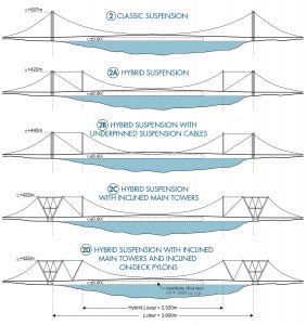
As a result of exploring different alternatives for hybrid suspension bridges, it was determined that hybrid options with Lsusp = 0.7 Lmax are the most efficient. The study compared classic suspension (Figure 2) with the following hybrid variations:
2a) hybrid suspension
2b) hybrid suspension with under-pinned suspension cables
2c) hybrid suspension with inclined main towers
2d) hybrid suspension with inclined main towers and inclined on-deck pylons
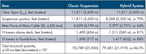
The reduction of the suspension length in hybrids allows using sags of 1/8 without requiring very high towers. For example, the result of replacing a classic suspension system for an 11,811-foot (3,600-m) span with a hybrid system (inclined main towers, Figure 2c) with a middle suspension part Lsusp = 0.7 Lmax = 8,268 feet (2,520 m) and the same 11,811-foot clear span (3,600-m) is illustrated in Table 1.
In trials of various sub-systems, the sub-system with minimum total structural quantity is hybrid with inclined main towers and inclined on-deck pylons (Figure 2d), providing 17.6% savings. However, for long spans of 9,843 to11,811 feet (3,000 to3,600 m), the inclined pylons-on-deck need to be about 1,214 feet tall (370 m) above the deck. Considering the ease of construction, the next most efficient sub-system, hybrid with inclined main towers but with vertical pylons on deck (Figure 2c), results in about 15% savings, is recommended for its overall efficiency, and is used for the example above. Additional advantages of this option are that the inclined tower legs result in suspension length reduction and the tower space structure provides more stability and better resistance to the higher reactions in super-long spans. Other sub-system configurations may be used if the designer and the builder find them efficient and viable in their detailed analysis.
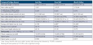
In addition to studying hypothetical bridges, the efficiency of hybrid alternatives can be studied and compared across existing long-span suspension bridges: the Akashi-Kaikyo Bridge, the Great Belt East Bridge, and the Izmit Bay Bridge. The results are listed in Table 2, along with the potential efficiency of hybrid systems.
For super long spans in areas with high winds, it is appropriate for the deck-girder system to be designed as a steel box with an aerodynamic shape; it may also benefit from additional side bracing with cables anchored to the shore. It would be more efficient to use two parallel bridge structures in some conditions, one for each traffic direction with some separation, interconnected with horizontal ties transforming the entire structure into a horizontal Vierendeel truss to increase the lateral resistance. If necessary, diagonals can be added between the two parallel structures, transforming it into a horizontal truss.
Conclusions
Based on current technical progress and development of suspension and cable-stayed bridges, suspension bridges can be expected to reach clear spans of 7,874 to 8,530 feet (2,400 to 2,600 m) in the near future. In comparison, cable-stayed bridges could reach 4,921-foot spans (1,500-m). Such design will require total tower heights of about 1,280 feet (390 m) for suspension systems or 1,411 feet (430 m) for cable-stayed systems.
Hybrid suspension systems will make possible even longer structure spans of up to 9,843 to 11,811 feet (3,000 to 3,600 m), incorporating an internal classic suspension system of only about 6,890 to 8,202 feet (2,100 to 2,500 m). Additionally, such hybrid structures could achieve a 10-15% efficiency of material. While these savings may not look substantial, for a 3-span bridge with an 11,811-foot main span (3,600-m) and a cost in the range of 4.5 to 4.8 billion dollars, the material savings would be 450-720 million dollars. More importantly, hybrid systems offer the possibility to build much longer spans with main element sizes in the range of those already used for shorter span structures with reduced bridge tower heights and reduced diameter of suspension cables. Hybrid systems in super-long spans (e.g., 11,811 feet; 3,600 m) would include unprecedented elements, like on-deck interior pylons taller than the Eiffel Tower to support the reactions of a considerable suspension portion (e.g., 8,268 feet, 2,520 m), a serious challenge. An actual project would require more detailed analysis and wind tunnel testing.
The results are consistent for a wide range of clear spans (2,461 to 11,811 feet; 750 to 3,600 m), making hybrid suspensions more efficient even in shorter spans of 2,297 to 4,921 feet (700 to 1,500 m). The future may see these types of configurations used to design and build longer span bridges where necessary, at a significant reduction in cost, materials, and efforts.■
This article is a continuation of Cable-Stayed Bridges, STRUCTURE, October 2020.