
Bay Area Project Redefines Traditional Build Methods By Aaron Miller and Erin Spaulding
With housing demands continuing to grow throughout the Bay Area, developers are looking for ways to deliver projects to market faster, without the added costs. One such solution is multi-story modular construction.
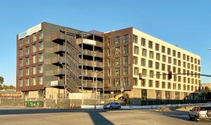
The Union project, a six-story residential building in Oakland, California, with five prefabricated wood construction levels, 110 market-rate apartments, parking, and ground-level retail, is that type of modular solution. Situated near the West Oakland BART Station, The Union offers access to public transportation and valuable housing for a strained market.
While this method of project delivery (also referred to as Factory-Built Housing in the State of California) can reduce construction schedules in half, it requires careful coordination between the design team, on-site contractor, and manufacturer to successfully execute its advantage: speed.
Modular Construction
Design for modular housing varies widely on materials used, whether the units are entirely built out pre-installation or finished on-site, installation limitations, and the specific manufacturer. That said, factories are predominantly using wood framing because it has historically been the most common material for prefabricated housing. Many of these multi-story modular factories have transitioned from prefabricated homes, education and worksite trailers, man-camps, etc.
Modular construction utilizes conventional gravity and lateral systems familiar to a multi-story wood residential building, including joists and beams supported by load-bearing stud walls for gravity and wood sheathed diaphragms and shear walls for lateral. The difference with modular construction is that each module comes with a floor, ceiling, and at least four walls. When stacked on top and next to each other, the assemblies are double-wide, and the workers lose access to make connections in some areas. Therefore, attention is required in the design to consider and understand access, sequencing, and the factory process, as well as designing for typical joists, beam elements, and studs.
With modular construction, two construction projects are happening in sequence. While the on-site portions are being built, the factory is building modules. A factory’s capacity is considered for timing with the site construction schedule, including site preparation, foundations, and, where included, the podium construction.
Factory Process
For factory processes, it is necessary to understand how the workstations are set up. These stations include floor framing, ceiling/roof framing, bearing wall framing, non-bearing wall framing, MEP installation, and vertical and horizontal finishes. Understanding the factory scope of work, completed or partial assemblies, and level of finish is important prior to design completion to provide proper load paths and connections made in the field. For example, the ceiling is built separately from the walls in the factory, typically with the ceiling gypsum already installed. Therefore, the ceiling needs to incorporate plywood bearing strips to ensure the ceiling gypsum is not in the load path and crushed when it is lifted onto the walls or when other live loads are added in the future.
The Union project manufacturer, Factory OS, located in northern California, built four modules a day on average. This rapid schedule requires prompt coordination and resolution for construction questions that arise during factory production. An issue identified at the floor station (often the first station) may no longer be accessible after 48 hours. It would need to be resolved after the module has finished its other stations and moved through the factory. During this project, the modular Structural Engineer of Record (DCI Engineers) and Factory OS directly communicated to quickly resolve issues and questions while keeping the rest of the design team and contractor in the loop. Confirmation RFIs were issued shortly after resolution for official documentation of these changes.
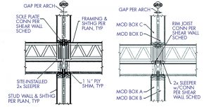
Figure 1 shows examples of a standard detail replicated in the construction documents, clearly identifying the in-factory work in the first detail and the necessary materials and attachments in the second detail for the required on-site work.
Construction Sequence
It is not uncommon to have two Engineers-of-Record (EOR) for a single project with the scope delineated between supporting structure and modular structure. For The Union, Murphy Burr Curry (MBC) designed the supporting structure and the site-built steel exterior stair. As the modular EOR, DCI designed and specified the anchors, including size and spacing, to connect bearing and shear walls to the transfer slab. Standard 5⁄8-inch-diameter anchor bolts secured flat 2x members that the modules would later bear on. To resist uplift forces at shear walls, custom steel connection plates for lightly loaded hold-downs were designed by DCI, while MBC provided the embeds for attachments. The attachment methods for the tie-down system (TDS) in the heavily loaded corridor shear walls were also provided by DCI, which includes panels to access the TDS-to-concrete embeds (once again designed by MBC) that would have otherwise been inaccessible after the module was lifted into place. Embeds were provided because the modular set sequence prohibited the use of conventional TDS anchor bolts, which would have protruded from the slab and interfered with setting the module.
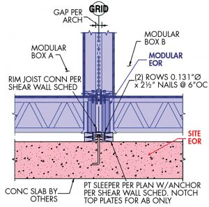
While the site EOR designed the steel embeds required for the custom plate and TDS hold-down connections, DCI agreed to specify the welds from the components above. Figure 2 shows a typical delineation in the scope between site EOR and modular EOR. Understanding these scope delineations is unique to modular construction and extends to the factory versus field installation. Other challenges for this project included designing in a high seismic zone like the Bay Area and the required ductility of connections. Modular systems share these challenges with traditional field-built wood construction. Still, they require special consideration for access because the connections are made after the fully finished modules are installed at the construction site.
Before construction even began, the team considered design for delivery and getting the general contractor involved earlier for feedback on the module set sequence. This required coordinating the on-site structural connections with the crane set sequence, which needed verification by the General Contractor (GC) as soon as possible. Based on crane availability, location, and space around the site, the GC may request a crane set order different from initial design assumptions. For The Union, the assumed set direction during design was east to west for the large building, but it ended up going west to east for access and staging, requiring engineers to switch the shear wall locations in the modular units after the building permit was issued. Late changes like this required a resubmittal to the State jurisdiction for approval. The modules were set starting at the site-built exterior stair (designed by site EOR) and then outward because of the new set order. However, the exterior stair had to be built after the module set to avoid interference with the crane swing.
To maximize the overlap in the construction schedule, thus saving total construction time, the modular units’ delivery time and the contractor schedule for having the site ready on time is critical. This requires frequent GC and modular manufacturer coordination, such as weekly coordination meetings on delivery timing and crane sequence. This is to ensure that if the timeline needs to be pushed, the coordinated schedules still work. Ideally, modules will arrive as the site is finished; however, the next goal is to have the modules ready and staged close by for immediate installation if there is a delay on the site.
Connection Access Challenges
Putting it all together is the last piece of the puzzle. Although making the on-site connections is considered “the last step,” it needs to be considered early in the design because access is extremely limited in modular construction compared to a traditional site-built wood structure. Specifically, the units typically arrive with interior finishes completed, including walls, ceiling, floor finishes, paint, trim and interior fixtures, and appliances, so there is no available access from the units’ interior without planning on unsightly access points or areas requiring field finishing. Instead, connections must be accessed from the exterior of the individual units and corridors left partially unfinished.
For The Union project, the only place to make connections were between the units during crane-setting the modules, from the corridor and from the exterior where the modules interface after the set was concluded. DCI designed the hold-down connections in the modules’ long direction to be accessed from the exterior or the corridor to avoid additional connections between the modular units and subsequent delay of the crane set. This was accomplished by designing the mateline shear wall (long sides of modules) to exterior wall interfaces (corners of modules) so that shear could be transferred to the exterior studs for hold-down connections, which had to be accomplished in the factory during wall installation.
A significant connection that required intense coordination was the floor rim joist connection to the sleeper at the long interface between modules. As shown in Figure 1, the upper right module (indicated as box D) is the last module placed in this detail, and there is no way to provide a connection from the floor rim to the sleeper below. In this detail, the crane set sequence was coordinated between the engineer, modular fabricator, and general contractor to ensure the module Box C contained the shear wall at this interface. This way, shear clips could be installed from the floor rim joist to the flat 2x sleeper below, which is then plate nailed into module Box A for a positive load path. The only time to install the shear clips was during the crane set, while the floor rim was accessible, after which they became inaccessible when the next adjacent module was set in the sequence.
As a result of the coordinated efforts, The Union capitalized on modular construction to expedite housing to the Bay Area’s high- demand market. While the speed of modular construction has its obvious advantages, it takes a combination of advanced communication, multi-discipline coordination, and a unique level of trust between project stakeholders to succeed.■
Project Team
Owner: Holliday Development
Architect: David Baker Architects
Modular Consultant: Prefab
Supporting Structures: Murphy Burr Curry
Factory: Factory OS
Contractor: Cannon