
The U.S. Pacific island territory of Guam is undergoing a massive transformation as part of a multi-billion-dollar realignment of Okinawa-based U.S. Marines throughout the Pacific. Once completed, the new Marine Corps Base Guam will be in the village of Dededo, but supporting facilities are being constructed at various locations around the island. One such facility is the first U.S. Marine Corps aviation support and maintenance hangar on Guam and is located at the North Ramp of Andersen Air Force Base. The new hangar is a 72,500-square-foot, $53.7 million facility that supports Marine Corps aviation squadrons. The project was delivered by Naval Facilities Engineering System Command as a design-build procurement. Designing for resiliency is essential on this remote island – regularly subjected to strong typhoons, large earthquakes, and a highly corrosive tropical environment. Equally important is ensuring the design can be efficiently constructed using limited available local labor and resources.
Building Description
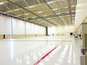
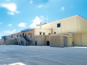
The overall facility is 414 feet long by 176 feet wide by 65 feet tall and consists of three areas: the hangar bay, the shop and maintenance area, and administrative spaces. The single-story hangar bay has interior clear dimensions of 325 feet by 125 feet by 39 feet (to the bottom of the bridge crane) with 46-foot-wide door pockets on each side of the door opening (Figure 1). The facility’s shop maintenance and administrative portions are located at the rear of the hangar in a two-story structure (Figure 2). The two-story structure’s exterior dimensions are 272 feet long by 50 feet wide by 33 feet tall.
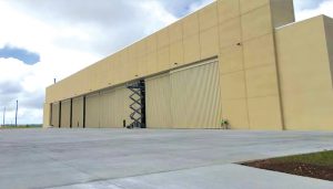
The main hangar doors can fully open, creating an uninterrupted 325-foot-wide opening. The 40-foot-wide door panels stack into pockets outboard of the hangar bay, four panels on each side. The door pocket enclosures support and protect the door panels and provide shear walls to stabilize the building’s front in the longitudinal direction (Figure 3).
The long span across the main hangar door opening, combined with heavy concrete roof and precast concrete cladding loads, required a steel box truss that protrudes 15 feet above the main hangar roof. This step-up creates a parapet-like effect on the hangar’s main roof, resulting in extremely high uplift and downward wind pressures.
The hangar bay’s interior has an overhead bridge crane with very stringent deflection criteria for the supporting structure (less than a couple of inches on spans greater than 100 feet), and the maximum variance between the crane rail supports cannot exceed ½ inch. Careful coordination with the crane supplier and steel fabricator was essential to meet these requirements.
Primary Structural Systems
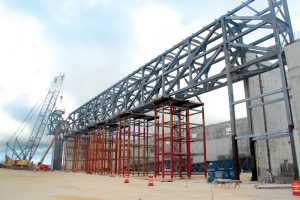
NAVFAC required the entire exterior building shell to be constructed from concrete to enhance long-term durability and reduce future maintenance needs. Given this directive and high seismicity, the design-build team’s most efficient option was a bearing wall system using cast-in-place concrete shear walls supported on shallow foundations. The main hangar bay roof is framed with steel wide flange purlins, metal deck, and concrete topping supported by structural steel trusses. The trusses are supported by a concrete wall at the back of the hangar and a structural steel box truss, comprised of heavy wide-flange sections, spanning across the hangar main door (Figure 4). Steel towers support the box truss on each end of the door opening, and 65-foot-tall reinforced concrete shear walls enclose the sides of the hangar bay. All structural steel, metal deck, and high-strength bolts are hot-dip galvanized and finished with a high-performance coating system.
Behind the main hangar bay, the two-story administrative and shops portion of the building is framed with precast concrete double tees with a composite concrete topping spanning the building’s width. Concrete shear walls support the double tees.
Typhoon Winds and High Seismic Criteria
The hangar is designed in accordance with the 2012 International Building Code (IBC) and the American Society of Civil Engineers’ ASCE 7-10, Minimum Design Loads for Buildings and Other Structures, for a 3-second gust wind speed of 195 miles per hour and seismic accelerations of SS = 2.79g and S1 = 0.68g. Wind speed-up effects due to the project’s proximity to a coastal cliff (topographic factor, Kzt, of 1.45) and the hangar designation as partially enclosed significantly increase the design wind pressures. Maximum components and cladding roof uplift pressures exceed 400 pounds per square foot. The structure is assigned to seismic design category D with a seismic response coefficient, Cs, equal to 0.37. Addressing both extremely high wind and seismic forces in a long-span structure is a unique challenge that requires a careful balance to arrive at an optimal structural system. One example is the addition of concrete topping to counteract high roof uplift loads. Whereas it is beneficial for resisting typhoon winds, the added mass has the opposite impact on seismic performance by increasing the building’s inertial forces. The optimum amount of concrete thickness was determined through analysis and design iterations.
Constructability Challenges
The constructability of the structural system using limited, locally available labor and resources was a major consideration. Since there are no steel fabricators on Guam, all steel was fabricated, galvanized, and shipped from the continental U.S. Careful coordination between the steel fabricator, erector, galvanizer, and design team was essential, which included fast-tracking the structural steel package to accommodate shipping to Guam. The primary trusses and box truss were constructed on the U.S. mainland and then broken down into individual members for shipping to minimize potential fit-up issues once in Guam.
A second challenge was the limited number of qualified welders in Guam. This was addressed by designing bolted steel connections wherever possible. Heavily loaded connections for the box truss required a considerable number of bolts, the largest of which had over 400 hundred bolts in one connection (Figure 5).
Construction of the hangar door pockets presented the third challenge. Since the entire hangar must be fully accessible, the door panels slide into pockets outside the hangar footprint. The individual door panels slide between the steel columns supporting the box truss, and, as a result, the columns have large unbraced lengths. Using steel braced frames on each side of the door pocket for lateral force-resistance was considered but ultimately abandoned due to difficulties meeting the stringent high seismic requirements with members having such long unbraced lengths. The final design consists of very thick special reinforced concrete walls that form the door pocket shell.
With wind pressures exceeding 200 pounds per square foot, the out-of-plane stability of the 65-foot-tall hangar side walls posed the fourth challenge. Three different options were initially explored: one-way walls spanning vertically from foundation to roof, two-way spanning walls with concrete pilasters, and two-way spanning walls braced within the wall clear height to the roof. The contractor selected the third choice to minimize the thickness and reinforcement in the walls without complicating the formwork. Five lines of sway frames, equally spaced across the hangar’s width, are used to brace the walls to the roof diaphragm.
The 325-foot-long box truss was designed and fabricated with a significant initial camber at mid-span that was expected to flatten as the box truss was progressively loaded. The camber was induced during fabrication by precisely adjusting the geometry of the individual members and connections. This large camber presented the final challenge – how to best sequence erection to ensure that, once the structure is complete, the estimated final camber is attained and the precast cladding panels are level and properly aligned. Developing a workable strategy involved close coordination between the design team, general contractor, cladding manufacturer, and precast erector.
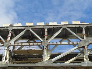
First, the box truss was erected and supported using six shoring towers. Next, the main roof trusses, purlins, and metal deck were set, and the concrete topping poured. The weight of the roof structure removed 6.25 inches of camber. The box truss was then preloaded with concrete blocks that approximated the precast panels’ weight to force the box truss to deflect into its final position (Figure 5). After each precast panel was aligned and erected, the concrete blocks representing the weight of that panel were removed. The box truss deflections were carefully monitored in the field over several months, and adjustments were made during construction where required.
As one of the most remote places in the U.S., Guam has been a strategic center for U.S. military operations in the Pacific for decades. The island is regularly subjected to powerful typhoons and large earthquakes, and, with relief support far away, the buildings in Guam must be durable, self-sufficient, and resilient. The Guam Aircraft Maintenance Hangar is one such resilient facility that supports forward operations and maintenance functions for the U.S. Marine Corps now and in the future.■
All photos courtesy of Pernix Guam, LLC.
Project Team
Executor/Client: Naval Facilities Engineering System Command – Pacific
Construction Manager/Contract Administrator: OICC Marine Corps Marianas
Special Inspector of Record: BASE
Architect of Record: BRPH Companies, Inc.
General Contractor: Pernix Guam, LLC
Precast Concrete Supplier: Rocky Mountain Precast, Guam
Steel Fabricator: R.F. Stearns, Inc.