
Rationale, Objectives, and Execution
While it is usually possible to demonstrate the safety of an existing structure through calculations based on general accepted engineering principles, this is not always the case. Sometimes there are structures for which calculations alone may not be sufficient to demonstrate fitness for intended occupancy or use. In such situations, in-situ load testing can provide valuable information about the performance of existing structures, and can take advantage of beneficial structural behavior not readily apparent with conventional computational methods.
The primary goal of load testing is to demonstrate the safety of a structure. Load tests do not determine the design strength or load-carrying limit. In general, load tests can be used to determine the ability of a structure to support additional loads, to establish the safety of structures with design or construction deficiencies or structures with damage or deterioration, to validate design approaches for and effectiveness of strengthening schemes, to gain knowledge on the behavior of a structure by accounting on the beneficial effects of “hidden” load paths, and to supplement, validate or “tune-up” analytical work aimed at understanding the behavior of a structure.
Part 1 of this two-part article discusses the rationale and objectives of in-situ load testing within structural evaluations of concrete structures, and presents methods for load application and instrumentation. Part 2 presents the load test procedures prescribed by the American Concrete Institute (ACI), and describes case studies that illustrate the use of in-situ load testing as a valuable tool in structural investigations.
Load Testing in the Evaluation of a Structure
The objectives of any structural evaluation are to establish the existing condition of the structure, identify issues affecting the structural performance, and develop and implement any remedial actions required. Very often, the evaluation of an existing structure requires performing structural analysis to investigate the ability of the structure and components to resist the load demands prescribed by the governing building code.
Frequently, the evaluation of existing structures requires a field condition appraisal to determine the condition of the structure. The information collected in the field is used to supplement the structural analysis conducted to establish the adequacy of the structure or components of the structure in question. However, in some situations, the results of the structural analysis may not be conclusive and a high level of confidence in the results cannot be achieved. In situations like these, in-situ load testing may be required to gain further knowledge about the behavior of the structure to conclusively establish its adequacy.
Load test programs can be expensive and, as such, they should only be used when analytical resources have been exhausted and when there is high confidence that the results of the load test can help with answering questions about the structural behavior not evident from other analyses.
The Load Test Program
Generally, a load test program involves performing the tasks described below.
Definition of Load Test Objectives
The engineer should clearly define the load test objectives. The objectives, benefits and risks associated with the load test program should be clear to all the parties involved (i.e. owners and building officials). Load tests typically have the following objectives:
- Demonstrate that the structure or structural element can safely resist the design loads with an adequate factor of safety against failure, and
- Demonstrate that the service loads do not cause deflections or crack widths that exceed industry standard limits, or preset values established for operation of a given structure.
Selection of Test Elements
Constraints due to site access, implementation cost, execution time, etc. require that the number of test areas or test elements is limited. Therefore, the portion of the structure or structural elements selected for testing need to be representative of similar areas or elements of the structure so that the load test results can be extrapolated to other areas. The selection process requires an exhaustive review by the engineer of the existing conditions, which may include evaluating parameters such as:
- Representative geometry (as-built cross sections and spans, and reinforcement)
- Representative distress (cracking patterns, deterioration, deflections, etc.)
- Representative Demand-Capacity ratios
Development of the Load Test Protocol
The load test protocol includes the loading procedures and the means to evaluate the performance of the structure during the load test and at completion of the load test. The load test protocol has two components that are dependent on each other: the loading procedure and the acceptance criteria.
The loading procedure describes how the structure will be loaded: load steps required to reach the ultimate test load magnitude, duration of each load step, loading and unloading requirements, hold period for the test load magnitude, etc.
The acceptance criteria describe the parameters to evaluate the performance and acceptability of the structure. These parameters can be qualitative or quantitative. Qualitative parameters are those that can be assessed visually, including formation of new cracks, widening of existing cracks, or other damage caused by the applied loads. Quantitative parameters are those that can be physically measured and can include deflections, strains, angles of slope, and crack widths.
The ACI Committees 318 and 437 prescribe two protocols for load testing of concrete structures: Monotonic Load Testing and Cyclic Load Testing. These protocols will be briefly described in Part 2.
Selection of Load Application Method
The applied test load should replicate the effects of the design load conditions (typically uniform loads). Dead weights such as sand bags, water in containers, or mechanical apparatus such as hydraulic jacks can be used to load structural elements. The selection of the load application method depends on load test objectives, site conditions, time constraints, equipment availability, etc. In general, the use of either dead loads or hydraulic jacks requires the engineer performing a detailed structural analysis to determine the appropriate test load layout and the load test setup to apply those loads. Various types of load application methods used for in-situ load testing are described later.
Structural Analysis
Any load test requires performing structural analysis before and after the load test. The pre-load test analyses are typically done to estimate the test loads and to determine the load layout. These preliminary analyses also provide information on how the structure may behave during the load test, and serve as a check to assess if the structure is undergoing excessive distress during the test. For instance, test deflections much larger than the analytical deflections may indicate that the structure is being damaged by the test loads, which may warrant halting the test.
The post-load test analyses, performed with a better understanding of the actual behavior of the structure, allow establishing the safety of the structure or determining a lower load rating, in case the acceptance criteria was not met.
Preparation of a Safety Plan
An important consideration when undertaking a load test is the safety of the personnel involved in the test, and of the building occupants that may be in areas adjacent to the test area. Test loads are typically higher than the service loads on the structure; therefore, there is a possibility of failure of the element or structure during a load test. Structural failure can result in collapse of the tested element which can compromise adjacent structural elements. Also, since test loads create large stresses in the structure, there is a risk for falling hazards such as pieces of concrete spalled from the structure, or for flying hazards such as strained pieces of the test apparatus.
Safety measures typically include the installation of shoring towers to prevent collapse of the structure in case of failure. There should be a gap between shoring and the test structure to allow the structure to deflect freely. The gap dimension should be selected based on the expected deflections obtained from the structural analysis. Thus, this gap should not be too large to preclude excessive deformation in case of failure, nor too small to prevent restraint when the structure deflects during the load test.
Methods of Load Application and Instrumentation
Loading using Water and Dead Weights
Dead weights or water can be used to load structural elements. Because of the relatively low specific weight of water, the use of containers (drums or cylinders) or reservoirs (pools) filled with water is typically feasible when the test loads do not exceed 200 psf. Figure 1 shows a load test using drums filled with water. The containers should be free of damage to prevent leakage, and stable when loaded to prevent flooding of the test area if a container breaks or tips over. A typical constraint for the use of water is the need for drainage near the test areas to dispose the water once the load test is completed. Disposal of water can be arduous. Pumps and hoses can be used to convey the water to distant drains but the unloading process may significantly slow down.
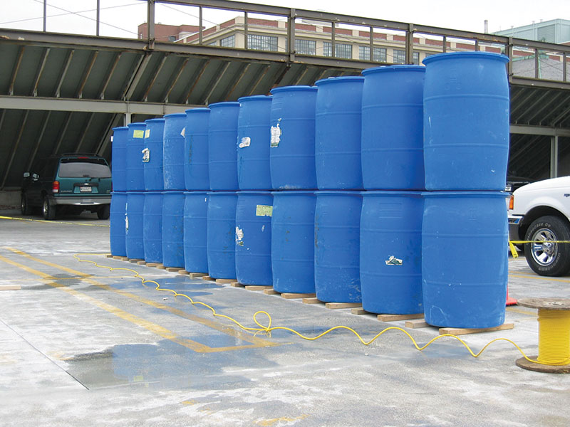
Figure 1. Load test of precast concrete planks with drums filled with water.
Materials with higher specific weights such as sand, bricks, steel plates, etc. can be used when the test loads are higher. These materials are typically placed in pallets, which facilitates their handling and application in a controlled manner. A constraint for the selection of dead weights is the ability of the test area and adjacent areas to adequately resist the loads caused by the equipment, typically forklifts, used to convey the loading material to the test area. Concentrated loads caused by the front axle of a loaded forklift can be significant and can have detrimental effects on the structure.
Loading using Hydraulic Jacks
When using hydraulic jacks, an adequate reaction must be provided by the existing structure and/or steel elements specially manufactured for the load test. The elements (new or existing) should have sufficient strength and stiffness to allow application of the test loads without adversely affecting the outcome of the load test. The selection of load application method using hydraulics depends on the test load magnitudes, geometry of the structure, and field constraints. Common methods are briefly described below.
- Push-down test method: One or more hydraulic jacks with extensions or appropriate supports are used to react against the structure above to create downward concentrated forces on the test element (push down). Figure 2 shows an overall schematic of this test method.
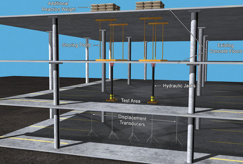
Figure 2. Push-down method.
- Pull-down test method: The hydraulic jack applies the loads using a reaction on existing elements below such as columns or beams, or micro piles driven in the soil or dead weights to effectively pull down the test element. Figure 3 shows an overall schematic of this test method.
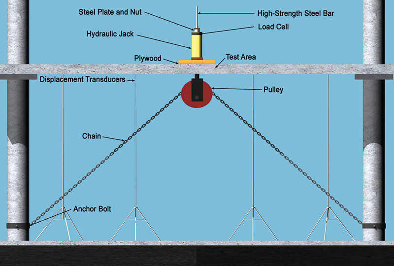
Figure 3. Pull-down method.
- Closed-loop test method: Using a self-reacting load condition within the test component, this method does not require resistance of external reactions. Figure 4 shows hydraulic jacks applying the load simultaneously to two elements by reacting against an existing beam supporting the test elements.
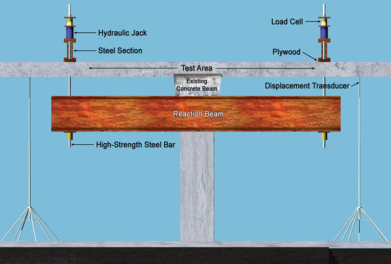
Figure 4. Closed-loop method.
Measuring Equipment and Data Recording
In order to obtain good and reliable results, the instrumentation to monitor the response of the structure during the load test should be carefully selected. When using electronic devices, all the data is typically collected with an automated data acquisition system to monitor the response of the structure during the load test. However, when using dead weights, water or dial gauges, data can also be manually recorded at the completion of each load step.
Load cells are typically used to monitor the load applied by hydraulic jacks. Load cells come in a variety of shapes, sizes, and capacities. Pressure transducers can also be used to measure fluid pressures in the hydraulic system, which can be calibrated and correlated to applied loads. Dead weights are typically weighed using scales prior to loading. When using water, water meters can be used to measure the amount of water introduced in the containers.
During load tests, movement and strains are measured at different sections of interest in the test element. Thus, deflections are commonly measured using linear variable differential transducers (LVDT) or dial gauges. Electrical resistance strain gauges are commonly used to measure strains. Strain gauges are bonded to the surface of the material for which the strain will be measured.
Inclinometers are also used to measure the rotation or slope of a test element, which can later be correlated to deflections.
LVDT’s placed across cracks can also be used to continuously measure crack growth (Figure 5). Optical comparators are also a useful device which is typically used to record cracks after each load step.
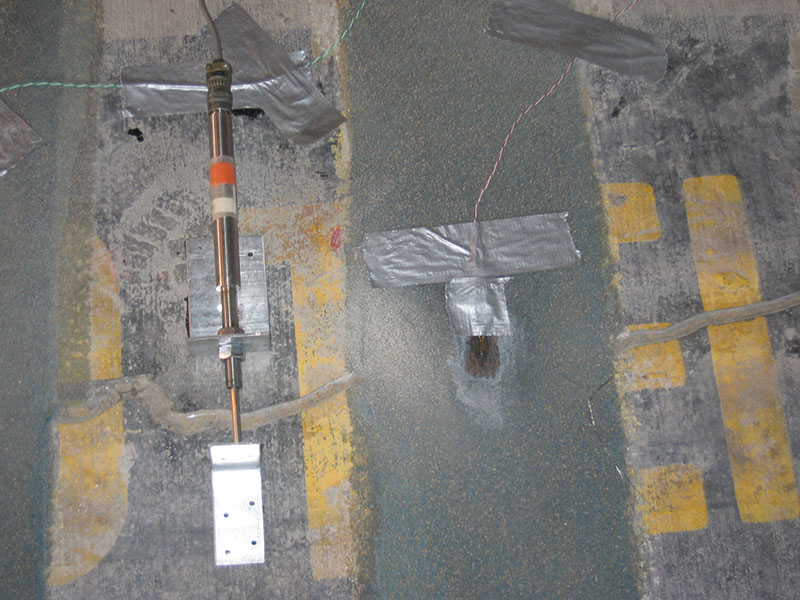
Figure 5. Strain gauge to measure strain in CFRP laminate and LVDT to measure crack growth.
In general, the accuracy of the measuring devices should be, as a minimum, 5% of the maximum value to be measured. Therefore, the engineer conducting the load test should always make preliminary calculations of the values to be measured in order to determine the appropriate instrumentation.
Part 2 of this article, scheduled for an upcoming issue, will disuss how the principles of load testing have been implemented.▪
The authors would like to thank NCSEA and the International Code Council for the use of these graphics, which first appeared in the book, Inspection, Testing, and Monitoring of Buildings and Bridges, Chapter 8. They are reprinted with permission.