
The Fast and the Slow
The crack patterns in broken glass and their fracture surface details describe the origination and energy intensity that caused breakage. This article discusses basic fracture technology of flat glass in architectural and structural glass assemblies, illustrating characteristic fracture surfaces and crack patterns. The objective is to provide information to engineers investigating glass breakage and tips for specifiers to avoid glass breakage problems.
Glass Material
Soda-lime silica flat glass sheets consist of silica sand, sodium carbonate, lime, metal oxides, and recycled glass. Heated to 1500 degrees Celsius, the mixture forms into a continuous ribbon “floated” on a long bath of liquid tin. An annealing process slowly cools the material to release internal stresses, resulting in the most common manufactured form of architectural flat glass.
Unlike solid material crystalline lattice structures with ionic bonds, such as ceramics, glass is an amorphous solid (i.e., not a supercooled fluid) relying on covalent bonds. Covalent bonds share electrons between atoms, typically breaking between 150 and 400 kilojoules per mole (kJ/mole). Glass covalent bond breakage energy is in the high range of 435 kJ/mole. In crystalline solids, ionic bonds transfer electrons between ions, typically breaking between 600 to 4000 kJ/mole. Whereas glass and ceramics share multiple performance properties, ceramics can have solid molecular geometry (from ionic bonding). Despite the difference in molecular geometry, the theoretical compressive strength of glass is in the same high range as metals and ceramics and metal materials. Glass ideally can develop up to 17 Gigapascals (GPa) or 2,466 kilopounds-force per square-inch (ksi) compressive strength. Glass tensile strength, however, is typically in the range of 10% its compressive strength. This is because, despite its apparent transparency, smoothness, and clarity, freshly manufactured glass is proliferated with surface imperfections unobservable to the naked eye. The severity and distribution of these microscopic “flaws” control the tensile strength of glass in combination with its characteristic Fracture Toughness.
Basic Glass Fracture Mechanics
Fracture Toughness is a material’s resistance to the opening of a sharp surface imperfection (e.g., a crack or fissure) where propagation occurs suddenly, uncontrollably, and quickly. Fracture Toughness is measured by the Critical Stress Intensity Factor, KIC. The Mode 1 (i.e., crack opening – Figure 1) Critical Stress Intensity Factor for glass is between 0.5 and 1.0 Megapascals – square-root meter (MPa-m½) or between 455 and 910 pounds-force per square inch square-root inch (psi-in½). Steel alloys have a value between 50 and 200 MPa-m½ (between 45.5 and 182.2 Ksi-in½), up to 400-times that of glass. With its relatively high Critical Stress Intensity Factor range, ductile steel alloys will undergo significant plastic deformation, stretching under tensile loading before breaking. However, unlike ductile steel, glass fails suddenly with little elastic deformation and no significant plastic deformation; it breaks in a sudden, brittle manner.
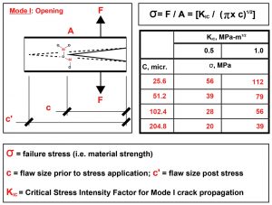
Surface flaws concentrate stresses and, combined with a low Critical Stress Intensity Factor, reduce glass strength. Moisture and tensile load cycling can accelerate flaw growth. Newly manufactured glass is typically stronger than “weathered” glass, which has additional flaws due to handling and exposure to moisture and/or cycled loading conditions. Figure 1 tabulates theoretical weathered glass breakage stress, with red text highlighting values for typical flaw size and Critical Stress Intensity Factor ranges.
Critical glass strength values are established based on material testing and statistical models to standardize safe working limits. Standards, such as ASTM E-1300, Standard Practice for Determining the Load Resistance of Glass in Buildings, and British Standard (BS) Euro norm (EN), Glass in Buildings: Determination of the Bending Strength of Glass, establish “allowable” glass edge and surface strength values used in building design and construction.
ASTM C1036, Standard Specification for Flat Glass, establishes architectural glass thickness tolerances and minimum optical quality, including limits on body, surface, and edge flaws. C1036 sets the standard for manufactured annealed (AN) glass. ASTM C1048, Standard Specification for Heat-Strengthened (HS) and Fully Tempered (FT) Flat Glass, establishes the range of Residual Compressive Surface Stress (RCSS) applied to AN glass by a heating and quenching process to produce HS and FT glass kinds. Through this process, HS glass achieves approximately double the tensile strength of AN glass, while FT achieves four-times or more of the tensile strength of AN glass. In addition to heat-treated glass products, chemically tempered glass is available for flat and curved glass applications.
Breakage is the conversion of the critical tensile stress into elastic strain energy at a surface or edge flaw. This strain energy breaks Silicon monoxide Si-O covalent bonds, thus increasing the flaw size and advancing it as a fracture through the glass body until the strain energy is expended. Glass breakage is due to one or the combination of two types of elastic strain energies applied: external and internal. Breakage due to applied external elastic strain energy occurs in AN, HS, and FT glasses due to mechanical and temperature loading. Breakage due to internal elastic strain energy occurs when RCSS (introduced to HS and FT glass during fabrication) is released into the glass body. When HS and FT glasses break due to applied stresses, the released elastic strain energy includes the sum of the applied external and internal stresses. The combination of these two elastic strain energies can be significantly higher than that of applied elastic strain energy by itself.
The length, characteristics, and quantity of glass fracture are directly related to the strain energy required to relieve applied external and/or internal stresses. The associated fracture velocity is also a function of the strain energy, material stiffness, and density. In Harold Edgerton’s Death of a Lightbulb / .30 Cal. Bullet (1936), a 0.30 caliber bullet is shown passing through a lightbulb. The speed of the gun’s report is approximately 343 meters per second (m/s) or 1,125 feet per second (ft/sec), the bullet’s speed is approximately 800 m/s or 2,624 ft/sec, and the terminal velocity of fracture development is approximately 1,500 m/s or 4,921 ft/sec. In the release of high elastic strain energy, glass breakage can occur far quicker than is discernable to the eye. Glass fracture can also progress at a low rate, progressing over weeks or months.
Initial Fracture Surfaces and Breakage Patterns
Breakage originates from an Initial Fracture Surface with distinct characteristics, described as follows (Figure 2):
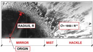
- The origin is a single point in the glass material from which a crack system originates;
- The mirror is a smooth, radiused area surrounding the origin;
- The mist is a frosted band surrounding the mirror;
- The hackle area extends from the mist band as ragged planes radiating away from the origin and towards the crack system.
The mirror’s smooth fracture surface forms at a low velocity and quickens from the mist through the hackle area as the fracture propagates into the surrounding glass body.
The Initial Fracture Surface provides critical information to describe glass breakage, including the mode of failure (mechanical or thermal) and the tensile stress at glass breakage. The mirror radius “R” provides a geometric dimension to calculate the stress at breakage through the formula, σ = 1950/R½.
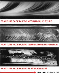
Beyond the Initial Fracture Surface, cracks form with characteristic surface “Wallner” lines (Figure 3), which are a succession of concave-shaped (primary/secondary) or curving (tertiary) lines produced when a crack front is momentarily altered by an elastic pulse. The direction of crack propagation proceeds from the concave to the convex side of these lines. Primary Wallner lines indicate discontinuities before fracture occurs. Secondary Wallner lines indicate the crack front as it approaches terminal velocity. Tertiary Wallner lines form due to an external shock or pulsed energy, triggering the onset of continuing crack growth. ASTM C1256 – 93 (Re-approved 2019), Standard Practice for Interpreting Glass Fracture Surface Features, provides an excellent reference with descriptions and images of fracture surfaces.
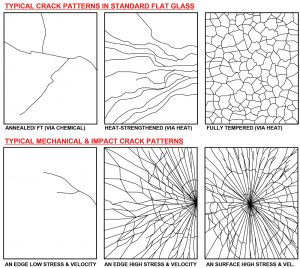
Crack patterns provide significant clues to describe glass breakage when coupled with information about the Initial Fracture Surface. In AN and chemically-tempered glass, cracks form as single or branching lines. In HS glass, cracks form as multiple single and joining branching lines. In FT glass, cracks form across all surfaces, creating a multitude of small fragments.
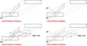
In all flat glass, low-stress cracks, due to mechanical stress (e.g., flexural), typically occur oriented non-perpendicular to glass edges and often non-perpendicular to glass surfaces. High-stress mechanical cracks have similar orientations with branching cracks that break away from the initial crack within two inches of the initial fracture surface. On the other hand, low-stress thermal cracks are typically oriented perpendicular to glass edges and surfaces; high thermal stress cracks have a similar orientation with branching cracks that branch from the initial crack within two inches of the initial fracture surface (Figure 4).
In mechanical and impact cracks, AN low-stress edge cracks form as meandering single/branching lines. High-stress edge and surface cracks form as many radiating lines with circumferential rings. Crack patterns in AN, HS, and FT flat architectural glass (Figure 5) are combinations and permutations of these typical configurations.
Special considerations for glass breakage relate to thermal stresses and spontaneous breakage. When AN glass heats up under direct or reflected solar radiation, glass central regions expand relative to colder edges. Thermally-induced hoop stresses can create tensile stress concentrations at critical edge flaws. AN glass is susceptible to thermal stress breakage if installed in partially shaded conditions, with integral or nearby heat-reflective or absorptive surfaces, and/or when glazed into materials that act as a heat sink. ASTM E2341, Standard Practice for Determining the Resistance of Single Glazed Annealed Architectural Flat Glass to Thermal Loadings, provides guidance to determine the potential for thermal stress breakage. Residual Compressive Surface Stresses in HS and FT glass assemblies typically make them resistant to thermal stress-induced breakage.
Spontaneous breakage can occur due to surface damage propagating through RCSS surfaces under cyclic loading or due to Nickel Sulfide (NiS) stone inclusion (or other batch impurities) in the manufactured glass material. NiS stone inclusions undergo an expansive phase change in their crystalline structure that, due to the relatively quick quenching of FT glass, has the potential to occur sometime after fabrication. HS glass quenching occurs slowly enough to allow NiS stone phase change and, like AN, does not suffer from spontaneous fracture due to NiS stone inclusions. The expansion in a NiS particle can cause a fracture in the body, which, when propagated to FT glass surfaces, suddenly releases RCSS throughout the glass body, causing breakage. The resulting starburst crack pattern features a pair of central pentagonal or hexagonal “cat-eye” or “butterfly” shaped particles whose shared fracture plane contains the NiS stone and the fracture origin. Not all cat-eye fracture patterns are due to NiS stone inclusions. Laboratory analysis such as Scanning Electron Microscopy (SEM) can positively identify impurities in the glass body to confirm the cause of spontaneous breakage.
Breakage Examples
The following projects provide examples where the crack pattern and initial fracture surface were vital in determining the glass breakage story.
Structural Laminated Glass Cantilever Tread Staircase
This project includes a multi-layered structural laminated glass cantilever tread staircase in a private residence (Figure 6). The tread specification considered conservative static and dynamic stair loads, plus post-breakage capacity for safety, using AN glass laminated with a stiff structural interlayer material. Installation details included set-screw level adjustment with a maximum setting torque specification into padded brackets, with each tread independently installed and test-loaded. One tread top glass lite cracked in a single line across the lite at an applied load significantly lower than as-designed. Recovery of the failed tread allowed investigators to measure the fracture mirror and to determine that the glass fractured at flexural stress over 7,000 psi, whereas the design allowed for no more than 1,500 psi.
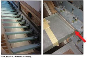
Further review determined that the supplied glass treads incorporated a flexible non-structural lamination interlayer material in place of the specified stiffer structural interlayer, resulting in glass non-composite performance and breakage at lower loading than as-designed. Replacing and load-testing all treads with glass laminated with the specified structural interlayer provided a resolution to the breakage problem. In this breakage example, initial glass fracture was a high strain energy event dissipating quickly due to excess loading of an improperly supplied laminated glass assembly.
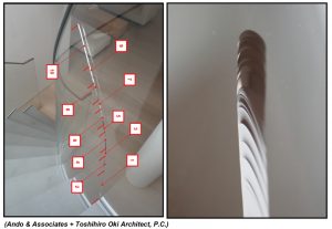
Curving Staircase Laminated Glass Handrail
This project includes a residential curving staircase with large chemically-tempered, laminated glass handrails (Figure 7). The design called for small joint finish dimensions and tight tolerances for handrail installation into base support shoes on the stair structure. Three months after completion, a single-line crack emerged within one of the laminated lites from the inner stringer base shoe. The crack propagated slowly over a period of 6 months, extending from the base shoe toward the handrail top edge. The owner was reluctant to remove the glass, and the installer was confident that removal would destroy the initial fracture surface. The slowly growing crack featured long, smooth fracture surfaces spaced by shorter groupings of tertiary Wallner lines. These fracture surface characteristics indicated intermittent decelerated and accelerated crack growth consistent with the owner’s stair use. Without access to the initial fracture surface, there was no way to confirm the exact cause of breakage. The possible single or combined cause of breakage included manufactured flaws, damage during handling and installation, over-constraint in the base support shoe due to tight tolerances, glass-to-metal contact, and mechanical loading from stair use. In this breakage example, initial glass fracture was a low- or high-strain energy event due to an unknown cause, followed by low-strain energy dissipating over an extended period.
Tips to Avoid Glass Breakage
The story of glass breakage is documented precisely in crack patterns and their fracture surface characteristics. As useful as these indications are for breakage investigators, designers and specifiers are more interested in avoiding breakage altogether. Here are five tips to assist in avoiding glass breakage in design:
- Design glass for loads to meet strength and serviceability requirements via standard methodology or first-principles analysis, including consideration for post-breakage performance.
- Avoid AN glass partial shading.
- Specify HS glass unless FT glass is required to meet code or contract requirements. When specifying FT glass, heat-soak to reduce the likelihood of spontaneous breakage.
- Allow for required construction tolerances and support movement.
- Avoid glass contact with hard objects during fabrication, handling, transportation, and installation.
If breakage does occur, the following steps are essential to maintain safety and to determine the cause:
- Control and make the area safe.
- Engage a glass expert to review the situation.
- Document and identify the crack pattern in-situ.
- Preserve the fracture origin for analysis.
- Provide design and installation history.
Conclusion
Crack patterns in broken glass, along with their fracture surface characteristics, provide a detailed account of the breakage story. Given the importance of glass in architecture and building construction, a basic engineering knowledge of material properties and fracture behavior is key to its proper specification and installation.■