
Note: Answers are based on ASCE 7-16, Minimum Design Loads for Buildings and Other Structures.
For diaphragm design, when do I apply overstrength (Ωo) load combinations and when do I apply the 25% increase on my diaphragm forces?
In general, the requirement to use overstrength load combinations is triggered when designing:
- Elements supporting the discontinuous wall or frames with an out-of-plane offset (horizontal irregularity Type 4) or an in-plane discontinuity (vertical irregularity Type 4). [Applies to structures in SDC B, C, D, E, and F]
- Elements contributing to the overturning resistance of cantilevered columns. [Applies to structures in SDC B, C, D, E, and F]
- Collector elements, splices, and their connections. [Applies to structures in Seismic SDC C, D, E, and F]
The requirement in Section 12.3.3.4 to increase the diaphragm forces by 25% is triggered when designing diaphragms in structures in SDC D, E, F with one or more of the following:
- Torsional irregularities (horizontal irregularity type 1a/1b)
- Reentrant corner irregularities (horizontal irregularity type 2)
- Diaphragm discontinuities (horizontal irregularity type 3)
- Out-of-plane offset irregularities (horizontal irregularity type 4)
- In-plane discontinuity (vertical irregularity type 4)
The 25% increase in seismic forces is to be applied to:
- Diaphragm connections to vertical elements of the seismic force-resisting system (SFRS)
- Diaphragm connections to collectors
- Collector elements
- Collector element connections to vertical SFRS
However, the exception in Section 12.3.3.4 states that load effects that include the overstrength factor need not be increased by 25%. Therefore, for a structure in SDC C-F, the collector elements and their connections only need to be designed for the load combinations, including the overstrength factor. Structures in SDC D-F that have a horizontal irregularity Type 1, 2, 3, or 4 or a vertical irregularity Type 4 shall be designed for the following forces:
- Diaphragm connections to vertical SFRS: 25% Increase
- Diaphragm connections to collectors: 25% Increase
- Collector elements: Increase by Overstrength Factor
- Collector element connections to vertical SFRS: Increase by Overstrength Factor
Finally, the code does not require the 25% increase or overstrength load combinations to design the diaphragm shears and moments.
Modified Response Spectrum for Site Class D and E sites with S1 ≥ 0.2 Exception.
Why does ASCE 7-16 require a site-specific response spectrum analysis? Is there any way to avoid it?
Research has shown that the use of only two response periods (0.2s and 1.0s) to define the Equivalent Lateral Force (and Modal Response Spectrum Analysis) design forces is reasonably accurate when the peak MCER response spectral acceleration occurs at or near 0.2s and peak MCER response spectral velocity occurs at or near 1.0s for the site of interest. However, the two-point spectrum is potentially non-conservative when the peak MCER response spectral velocity occurs at periods greater than 1.0s, particularly for structures on softer soil sites and where the seismic hazard is dominated by large-magnitude events.
During the ASCE 7-16 cycle, there was insufficient time to adequately define a full spectrum capturing the required modifications. As a result, an interim solution was provided: a geotechnical engineer is to provide a site-specific response spectrum for certain sites. The requirement for a site-specific analysis is triggered when assigning a site coefficient Fa or Fv. Specifically, for softer soils at high seismic regions, a requirement to see Section 11.4.8 is noted. Section 11.4.8 requires a site-specific analysis.
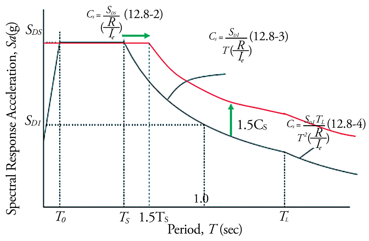
However, there are some relevant exceptions to this requirement. The most often used exception is for structures on Site Class D and E sites with S1 ≥ 0.2, provided Cs is determined by Eq. 12.8-2 for T ≤ 1.5Ts and taken as 1.5 times value computed by Eq. 12.8-3 for TL ≥ T > 1.5Ts or Eq. 12.8-4 for T > TL. This requirement forces the use of the constant acceleration equation, Cs = SDS/(R/Ie), for structures with T < 1.5Ts and the amplification by 1.5 of the constant velocity, Cs = SD1/T(R/Ie), and constant displacement, Cs = SD1TL/T2(R/Ie), equations.
Both ASCE 7-16 Supplement 1 and forthcoming Supplement 3 provide necessary clarifications to the footnotes of the Fa and Fv tables. These updates clarify that it is acceptable to use Fa and Fv values to calculate Ts and for the calculation of SD1 when the exceptions of Section 11.4.8 are used.
ASCE 7-22 will introduce a multi-period response spectrum, eliminating the need to perform a site-specific ground motion hazard analysis. This 22-point response spectrum will be publicly available via a web-based tool to provide acceleration parameters, including SMS, SM1, SDS, and SD1.
Can you clarify the difference between the two methods available to calculate redundancy, ρ, for my building?
Historically, many structures were engineered utilizing moment connections at all beam-column joints. Subsequent increases in labor cost and the availability of members with large section properties led to engineers concentrating SRFS in a few large elements. Damage from the 1994 Northridge earthquake was concentrated in these buildings with low redundancy. The code was then modified to encourage increased redundancy for structures in Seismic Design Categories D, E, and F. For structures with low inherent redundancy, the required design forces are amplified by 30% to increase strength and resistance to damage.
There are several conditions for which the redundancy factor, ρ, is permitted to be taken as 1.0, including for structures in SDC B and C, for drift calculations, for non-structural component forces, collectors, overstrength load combinations, and diaphragms.
For structures assigned to SDC D and having extreme torsional irregularity (Type 1b), ρ must be taken as 1.3. For other structures assigned to SDC D and for all structures assigned to SDC E or F, ρ must be taken as 1.3 unless one of the following two conditions is met. If one of the conditions below is met, ρ is permitted to be taken as 1.0.
- Method 1: Removing an individual element (brace, beam-to-column connection, shear wall or wall pier, and cantilever column) of the SFRS does not decrease the story strength by more than 33% and does not trigger an extreme torsional irregularity. This check only is required to be done at the stories resisting more than 35% of the base shear.
- Method 2: The structure must have two bays of SFRS perimeter framing on each side of the structure in each orthogonal direction. This method is only permitted for structures with no horizontal irregularities and only must be checked for stories resisting more than 35% of the base shear.
When doing modal response spectrum analysis (MRSA), why does ASCE 7-16 require me to scale my base shear to 100% of equivalent lateral force (ELF) procedures? Previously, where the combined response for the MRSA base shear was less than the ELF base shear, I only had to scale my forces to 85% of ELF.
Recent studies of building collapse performance, such as those of the Applied Technology Council’s ATC-63, ATC-76, and ATC-84, show that designs based on the ELF procedure generally result in better collapse performance than those based on MRSA with the 15% reduction in base shear included. Also, many of the designs using scaled MRSA did not achieve the targeted 10% probability of collapse given MCE ground shaking. While scaling to 100% of the ELF base shear does not necessarily achieve the intended collapse performance, it does result in performance that is closer to the stated goals of ASCE 7.
Does ASCE 7 require foundations to be designed for the overstrength factor?
Typically, ASCE 7 does not require overstrength to be used for foundation design. When designing elements supporting discontinuous walls or frames, overstrength is typically provided for the design of the connections to the foundation but not taken into the foundations.
One notable exception is in ASCE 7 Section 12.2.5.2, Cantilever Column Systems, in SDC B, C, D, E, and F. When designing a cantilever column system, the foundations used to provide overturning resistance at the base of cantilever column elements must be designed for overstrength load combinations.
A second exception of overstrength required in foundation design is in ASCE 7 Section 12.13.8.5 for pile anchorage requirements for SDC D, E, F. For piles required to resist uplift forces or provide rotational restraint, anchorage into the pile cap must be designed to resist the axial tension force resulting from the seismic load effects including overstrength.
Please note that the California Building Code modifies ASCE 7 Section 12.13.1 for certain structures (schools, community colleges, and hospitals) to require the foundation to have the strength to resist the lesser of the following seismic loads the lesser of:
- The strength of the superstructure elements
- The maximum forces that can be delivered to the foundation in a fully yielded structural system
- Forces from the Load Combinations with overstrength factor
Why do the provisions in Chapter 12 of ASCE 7 not mention SDC A?
To simplify the provisions, particularly for engineers designing structures in SDC A, there is no need to use Chapter 12. Instead, these structures must be designed to Section 11.7. This section points the engineer to Section 1.4, General Integrity, which has basic requirements for load-path connections, lateral forces, connections to supports, and anchorage to walls.
Why is there a seismic importance factor, Ie = 1.25 in Table 1.5-2, but only importance factors of 1.0 and 1.5 in Chapter 13?
The importance factor for seismic (Ie) is based upon Risk Category and the associated Life Safety, Hazard, and Essential nature of the structure. For building design, Ie = 1.0, 1.25, or 1.5, but for non-structural components (Chapter 13), Ip = 1.0 or 1.5, depending on Risk Category, SDC, component function, weight, and location. It is important to note that Ip might not equal Ie, and, in some instances, Ip may be less than Ie.
I have a building with special reinforced concrete shear walls, and I would like to classify it as a building frame (R=6) rather than a bearing wall (R=5). What is the difference between a building frame and a bearing wall?
ASCE 7 defines each system as:
- Bearing Wall System: A structural system with bearing walls providing support for all or major portions of the vertical loads. Shear walls or braced frames provide seismic force resistance.
- Building Frame System: A structural system with an essentially complete space frame providing support for vertical loads. Seismic force resistance is provided by shear walls or braced frames.
Several sources have attempted to clarify the distinction of what qualifies as “major portions of the vertical load.”
The Structural Engineers Association of California (SEAOC) Blue Book describes a method for detailing integral beams and columns within shear walls. The integral beams and columns must be capable of carrying the gravity loads of the portions of the wall damaged in a seismic event. This approach can be used to justify a building frame system with an enhanced R-value.
The National Earthquake Hazards Reduction Program (NEHRP) Provisions note that a building frame is a system where the gravity loads are carried primarily on columns, not walls, while allowing minor portions of the gravity load to be carried on bearing walls, but not more than a few percent of the building area.
When must my foundations be interconnected with ties? Can I use lateral soil pressure on my pile cap to provide the required restraint?
In SDC C, D, E, and F, structures utilizing a deep foundation system, individual pile caps, drilled piers, or caissons must be interconnected by ties per sections 12.13.7.2 and 12.13.8.2. All ties must be able to resist (in tension and compression) a force equal to 0.1SDSD, where D is the dead load of the larger pile cap or column dead-plus-live load.
Per section 12.13.9.2.1.1, for liquifiable sites and SDC E and F, individual footings shall be interconnected by ties in accordance with Section 12.13.8.2.
These requirements highlight the importance of the foundation system, acting as an integral unit, not permitting one column or wall to move independently from the rest of the structure. ASCE 7 requires that pile caps (and footings in SDC E, F) be tied together to attain this performance. This requirement is especially important where the use of deep foundations is driven by the existence of soft surface soils.
ASCE 7 does permit the required restraint to be provided by a slab-on-grade or confinement by competent rock, hard cohesive soils, very dense granular soils, or other approved means. However, relying on lateral soil pressure on pile caps is not recommended as ground motions are highly dynamic and may vary between structure support points during a design-level seismic event.
Can you clarify when I should be using Chapter 13 versus Chapter 15?
Section 15.3 represents a clear delineation between Chapter 13 and Chapter 15, where a nonbuilding structure is supported by another structure. When the supported nonbuilding structure’s weight is less than 25% of the combined effective seismic weights of the nonbuilding structure and supporting structure, the design seismic forces of the supported nonbuilding structure are determined according to Chapter 13. The supporting structure is designed to the requirements of Chapter 12 (if a building) or Section 15.5 (if a nonbuilding structure), with the weight of the supported nonbuilding structure considered in determining the effective seismic weight, W.
Even with the 25% threshold described in Section 15.3, there are non-structural components and nonbuilding structures common to both chapters. Some examples include billboards and signs, bins, chimneys, conveyors, cooling towers, stacks, tanks, towers, and vessels. The recommended reference for determining whether to use Chapter 13 or Chapter 15 is Nonstructural Component or Nonbuilding Structure? (Bachman and Dowty, 2008). That article suggests three ways to differentiate between non-structural components and nonbuilding structures:
- Size: Non-structural components are typically small, usually less than 10 feet in height.
- Construction: Non-structural components are typically shop fabricated.
- Function: Non-structural components are primarily designed for functionality, while nonbuilding structures are primarily designed to maintain structural stability.
I heard the requirement to consider accidental torsion is gone in the ASCE 7-16 Standard. Is this true? Why?
ASCE 7 has historically required a minimum eccentricity of 5% of the width of a structure perpendicular to the direction being considered to any static eccentricity computed using idealized locations of the centers of mass and rigidity. This requirement is because the locations of the centers of mass and rigidity for a given floor or roof typically cannot be established with a high degree of accuracy because of mass and stiffness uncertainty and deviations in design, construction, and loading from the idealized case.
However, ASCE 7-16 provides a new exception in Section 12.8.4.1 that provides relief from the accidental torsion requirements for buildings that are relatively insensitive to torsion. This provision permits the exclusion of accidental torsion moments when determining the seismic forces for the design of the structure, except for the following cases:
- Structures assigned to SDC B with extreme torsional irregularity: type 1b.
- Structures assigned to SDC C, D, E, and F with a torsional or extreme torsional irregularity: type 1a or 1b.
This relief is supported by research that shows that the inclusion of accidental torsion has little effect on collapse probability for low SDC structures without Type 1b horizontal structural irregularities and for high SDC structures without Type 1a or 1b irregularities.■
Reference
Bachman and Dowty, Is it a Nonstructural Component or a Nonbuilding Structure?, STRUCTURE, July 2008.