
Designing a drive-through canopy may not sound very exciting to most engineers. Finding out it is a drive-through for business jets at a high-altitude airport with hurricane-force wind speeds can quickly change that first impression. The 132-foot clear span arched trusses supporting the 40-foot-high aircraft canopy were the most prominent part of this unique project but far from the only design challenge.
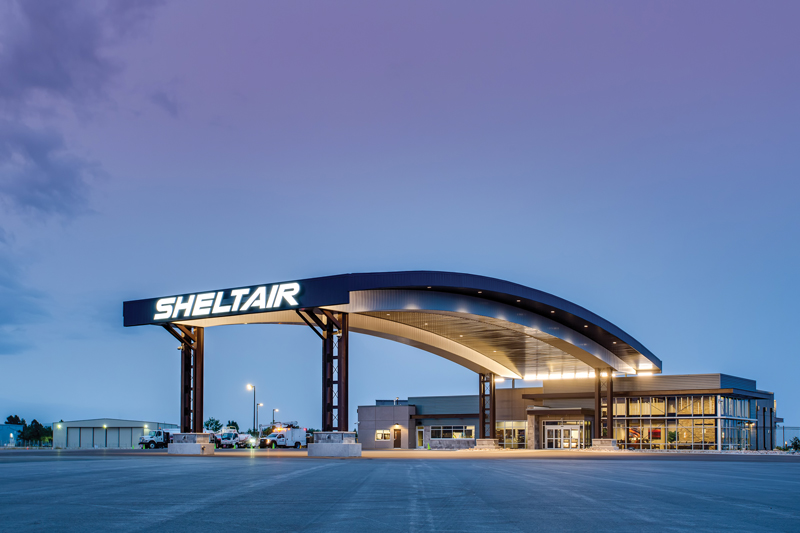
Sheltair’s state-of-the-art facility welcomes pilots and passengers at Rocky Mountain Metropolitan Airport. Photo by Bob Beresh, courtesy of Sheltair.
Project Scope
When Sheltair decided to expand its aviation network footprint with its first Fixed Base Operator (FBO) facility west of the Mississippi River, they partnered with Tectonic Management Group and Robbins Engineering Consultants as their architect and structural engineer of record, respectively. The Rocky Mountain Metropolitan Airport project in Broomfield, Colorado, included a new 35,000-square-foot hangar, a new 10,400-square-foot FBO building, and arched steel drive-through canopies – one for cars at the street entrance and the other for jets on the aircraft side. The FBO provides a passenger lounge, dedicated office space, conference rooms, restrooms, and dedicated areas for the operation of staff and line service. At 10,088 square feet, the aircraft canopy was almost as large as the building it served. At 15 feet taller than the FBO, both factors made the canopy readily visible to incoming pilots.
Design Challenges
The first challenge was due to the winds coming down the slopes of the nearby Front Range mountains. The 155-mph design wind speed (3-second gust) was comparable to the sustained wind speeds of a Category 4 hurricane. For comparison, that exceeds the design wind speeds for Risk Category II buildings in the hurricane-susceptible areas along the Texas Gulf Coast and much of the Atlantic coast. Despite being an open structure for planes to pull under for passenger loading and unloading, the canopy on the building’s airfield side still represented a large surface area for wind. The design team investigated several options before deciding on arched trusses supported by built-up laced columns (Figure 1). Twin W24x192 columns, 4 feet apart with round bar X-bracing and W8 struts between them, formed each of the 4 built-up columns. The arched trusses were 6 feet deep, using WT12x88 chords and double angle webs.
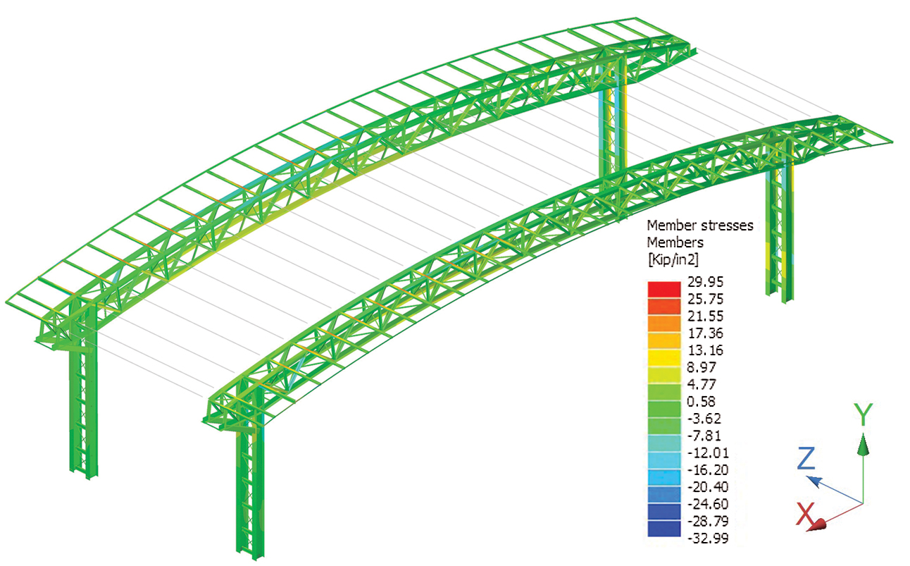
Figure 1. RAM Elements model of the high canopy for aircraft.
The 132-foot clear span had one field-bolted splice point near midspan. Each end of each truss was attached to the W24 column’s inside flange via bolted endplate moment connections (Figure 2). 10- and 20-foot cantilever truss sections were similarly attached to the outside flanges of the columns. Vertical X-bracing installed between each pair of trusses, as well as angle lacing in the planes of both top and bottom chords, formed a space truss at each set of built-up columns. This became the moment frame in the long direction. Each pair of laced columns function as cantilevered vertical trusses in the orthogonal axis. Concrete tie beams joined the columns in the long direction to resist the arches’ thrust under gravity loads.
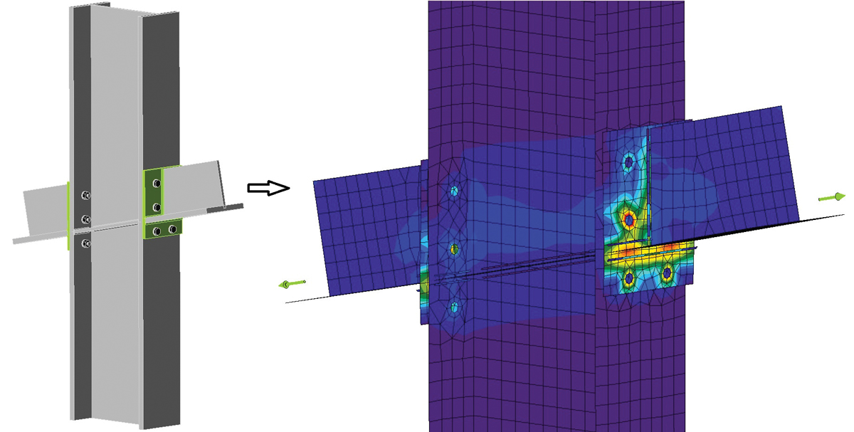
Figure 2. WT truss chord connected to the W24 column via endplates analyzed in Idea Statica
Connection. Cantilever to left of column, backspan to the right.
The FBO building had various discontinuities in the diaphragm that required careful cross-checking of design software results to ensure the complete roof-to-ground load path was checked. Similarly, the arched open structure of the canopies required extensive hand calculations to determine appropriate wind loads to be applied to the analytical models of the canopies. While there are wind external pressure coefficients in ASCE 7-16, Minimum Design Loads for Buildings and Other Structures, for enclosed structures with arched roofs (ASCE Fig. 27.3-3) and open structures with gabled roofs (ASCE Fig. 27.3-5), there are not yet any published for open structures with arched roofs. Therefore, the double-pitched open roof condition with slopes set to the arch slopes at the supports was used to model the actual configuration. The natural frequency was determined by modal analysis to verify the structure was not dynamically sensitive so that the assumption of a rigid structure under wind loading was appropriate.
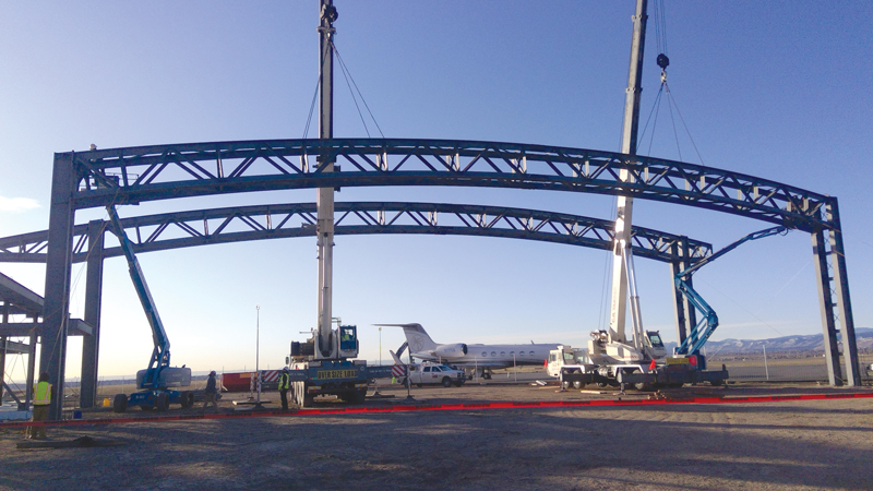
Figure 3. Two cranes were used to set the canopy trusses in place.
Extensive coordination was needed early to avoid rework on the trusses while accounting for shipping restrictions, crane capacities to lift them in place, and the optimum quantity of segments. After discussions with the architect and erector, one shipping splice near the midspan was adequate. Each pair of trusses was then assembled on the ground with bracing installed and set in place as a single unit with two cranes (Figure 3). Splice joints were designed as slip-critical connections with oversized holes to allow for easier fit-up of the unwieldy truss sections. Exposed structure at both arched canopies and in the FBO atrium was considered Architecturally Exposed Structural Steel (AESS) Category 3 (feature elements in close view). Establishing specific expectations for the AESS based on the American Institute of Steel Construction’s (AISC) recommendations in their Code of Standard Practice (AISC 303-16, section 10) helped minimize problems in that area.
Due to the presence of over 20 feet of expansive fill materials at the site underlain by expansive claystone prevalent in that area, the FBO building sits over a crawlspace with the elevated steel-framed ground floor supported on drilled piers extending a minimum of 18 feet into unweathered bedrock.
Lessons Learned
- The reduction in wind pressures due to elevation can be significant and should not be overlooked. With a field elevation of 5,673 feet above sea level, that equated to an 18% reduction in wind pressure for this project. While this reduction is new to the body of the ASCE 7 standard, it has been in the Commentary for many years and is derived from fundamental physics, so there is no reason not to take advantage of it.
- Care must be taken in laying out joists and deck on curved support framing. There are limits to how much corrugated deck can be bent in the strong axis; not accounting for that can add significant cost and time delays for special third-party crimping of the deck. As a result, several design iterations were required to balance the joist spacing, deck gage, and panel spacing of the large structural steel trusses supporting the joists to be compatible with field-bending the deck to the truss radius. Also, because the rolled W-beams of the smaller car canopy were a different radius, the joist spacing and deck gage were different at that canopy to accommodate field bending the deck.
- Be aware of jurisdictional differences in building code adoption. In this case, the airport’s mailing address is on Airport Way in Broomfield, CO, which is in Broomfield County. At the time of the project, both the city and county were still using IBC 2015, which is based on ASCE 7-10. However, the county line cuts through the airport property, with the airport mostly in Jefferson County, which had already adopted IBC 2018 at that point. This, in turn, changed the applicable wind provisions used from ASCE 7-10 to 7-16.
Conclusion
In the end, the client made a bold entrance into a new regional market. The high arched canopy provides an unmistakable landmark for pilots while also shielding customers from this high-altitude mountain airport’s harsh weather. And careful structural design and coordination ensured a smooth construction process and a realized architectural vision – a win-win for all parties.■
Todd Robbins is a Principal at Robbins Engineering Consultants in Little Rock, AR.
(trobbins@robbins-engineering.com)
Jason McCool is a Project Engineer at Robbins Engineering Consultants. (jmccool@robbins-engineering.com)