
Transforming a Neighborhood with Mass Timber Construction
The burgeoning Inner East District of Portland, Oregon, has experienced a transformation within the past ten years and, with it, a surge of new multi-family and office construction. Within this activity lay a small 9,000-square-foot bermed site, an artifact of a newly completed roadway realignment to connect westbound traffic to the Burnside Bridge – a primary link over the Willamette River into downtown. While useful as a staging and lay-down area to facilitate new building construction around it, project partners Key Development, Andersen Construction, and Skylab Architecture saw potential in the small hemmed-in site and recognized its prominent location and importance as a gateway to the newly created neighborhood. Through 17 months of planning and design and another 14 months of construction, the result of that vision is Sideyard – a nearly 25,000-square-foot office and retail building that serves as a showcase of Oregon-sourced mass timber construction (Figure 1).
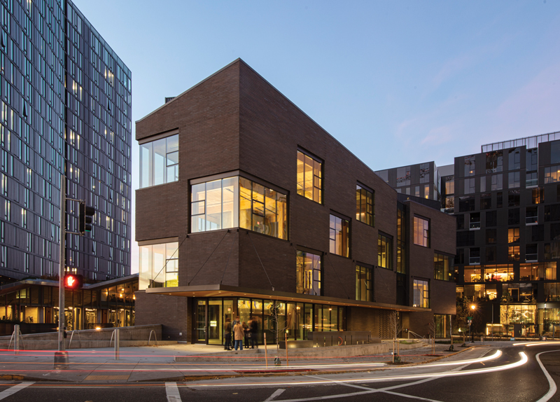
Figure 1. Sideyard makes stunning use of the leftover site.
Sideyard is five stories tall and slightly wedge-shaped in plan, measuring approximately 150 feet long in the north-south direction and a maximum of 56 feet wide in the east-west direction. The foundation consists of simple reinforced concrete shallow spread, strip- and mat-slab footings. The bottom-most level is a daylit basement facing Third Avenue to the west, incorporating a non-structural reinforced concrete slab on grade. Reinforced concrete basement walls restrain a single level of retained soil to the east and south. Reinforced concrete walls also surround two interior stair cores of identical size to resist wind and seismic lateral forces.
At the building roof and floors, the primary structural system consists of 5-ply cross-laminated timber (CLT) panels, up to 10 feet wide and 40 feet long. The panels span to periodic glued-laminated timber beams varied in size, up to 8.75 inches wide and 27 inches deep, and spaced at approximately 15 feet on-center. Except where framing into concrete walls, the beams span to and are, in turn, supported by glued-laminated timber columns measuring 10.75 inches by 13.5 inches in cross-section. A 4-inch-thick reinforced concrete topping slab at Level 2 provides sufficient diaphragm capacity to facilitate the transfer of lateral loads from the central core walls to the longer and stiffer basement walls. This topping slab also allowed for a polished concrete floor finish at Level 2 – something desired by the project partners. The remaining floors are topped with a non-structural assembly incorporating gypcrete and a sound insulation mat to provide the requisite acoustic characteristics. The columns and underside of all floor and roof structures remain exposed to view, maximizing the natural wood finish’s beauty. All CLT panels and glued-laminated timber members are of Douglas Fir-Larch species and were furnished by D.R. Johnson of Riddle, Oregon.
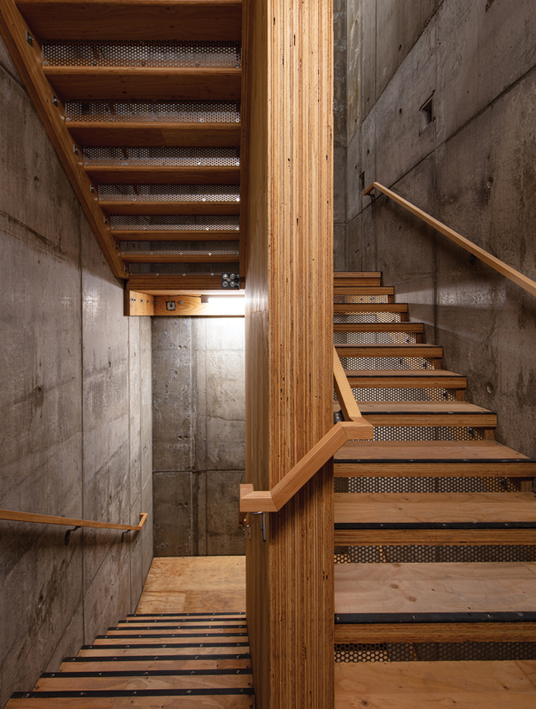
Figure 2. Stairway constructed of mass plywood.
Construction within the stair cores makes almost exclusive use of yet another mass timber product – mass plywood panels (MPP) by Freres Lumber Company, Inc. of Lyons, Oregon. Three-inch-thick mass plywood treads span between the inside face of concrete core walls to a central, full-height, 7-inch-thick MPP spine wall. The 7-inch-thick mass plywood panels are also used for the primary and intermediate stair landings. All mass plywood remains exposed within the stair cores (Figure 2). Sideyard is one of the first projects to employ mass plywood in a structural application, presenting a unique challenge, as the authority having jurisdiction was unfamiliar with the material.
When designing with exposed mass timber, it is essential to understand construction types early as fire protection requirements may dictate member sizes, panel thicknesses, connection concealment requirements, and, therefore, cost. Sideyard is Type IIIA construction, and structural members and connections are required to maintain their required load capacity after a 1-hour fire event. Accordingly, structural calculations completed in accordance with the American Wood Council’s Technical Report No. 10, Calculating the Fire Resistance of Exposed Wood Members, consider a 1.8-inch-thick sacrificial char layer on all exposed mass timber member faces and a protective 1.5-inch-thick char layer around mass timber member connections. Beam and column member sizes and CLT panel thicknesses were, in some cases, driven by these fire resistance considerations.
The exterior façade is a mixture of CMU veneer, large storefront windows, and curtainwall, and extends high above the roofline with braced parapets. Except for their self-weight, exterior walls are non-load-bearing. Resistance against out-of-plane wind and seismic forces is provided by a light wood-framed stud wall gapped at the underside of CLT panels above to accommodate vertical deflections and interstory drifts. As required in Type III construction, the light wood framing within the exterior wall assembly is fire-retardant treated. The CMU veneer predominantly rests atop steel ledger relief angles secured to the edge of CLT panels at each floor and the roof. At Level 3, large floor openings along the east and west sides led to the introduction of hollow structural steel beams to provide vertical and lateral restraint of the exterior wall assembly at those locations. Along the east side, these steel beams are also integral to a large steel-framed canopy, the front edge of which is further supported by diagonal tie rods secured to the edge of the CLT panels above at Level 4.
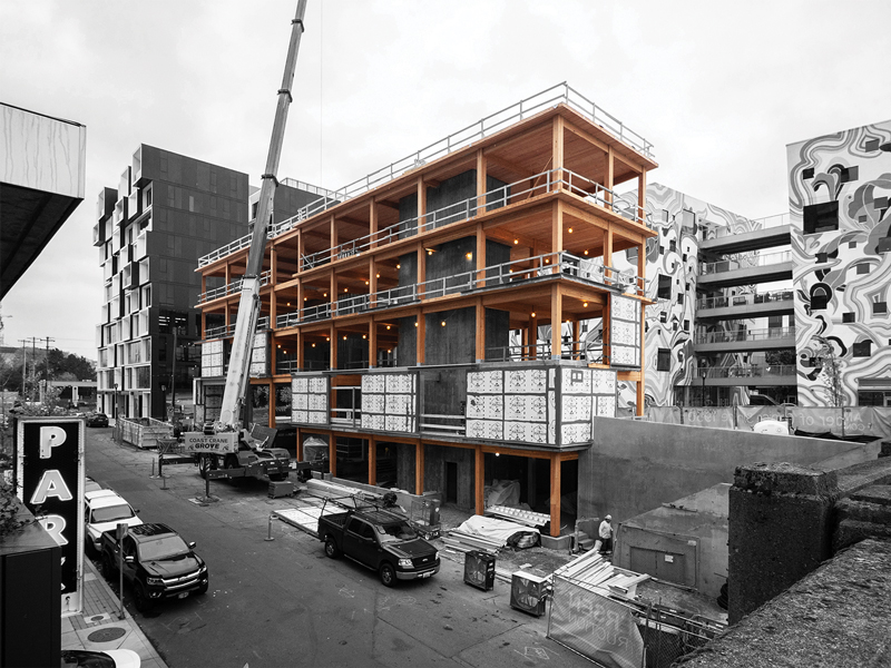
Figure 3. Exposed timber structure prior
to cladding installation.
A significant advantage of mass timber is the ability to shop-fabricate pieces for ease and speed of erection. This was particularly important at the Sideyard site. Despite having served as a staging area for previous nearby projects, it had very little remaining available space to stage its own construction materials (Figure 3; A timelapse video of Sideyard’s construction is found at https://vimeo.com/304267049). Structural members were shop-fabricated to the maximum extent possible by CutMyTimber, Inc. The ends of glued-laminated beams and faces of columns were furnished with premanufactured Ricon-series connectors (metal plates that connect in a dovetail-like manner) by Knapp AG, of Graz, Austria, to facilitate tight-fitting and concealed field connections between them (Figure 4).
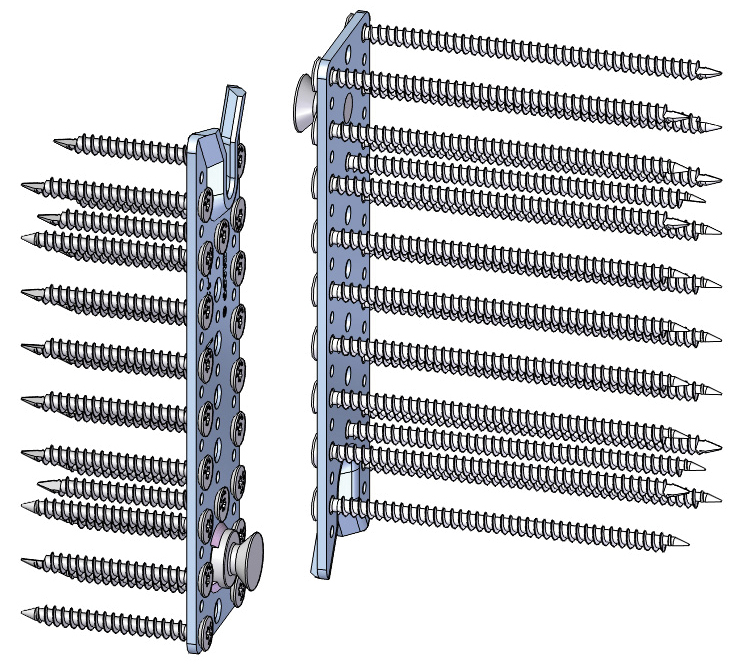
Figure 4. Glulam beam ends and
column faces were both furnished
with premanufactured Ricon-series
connectors to facilitate tight-fitting and concealed field connections.
Where higher load demands dictate, these connectors are doubled in a staggered configuration. Custom shop-fabricated concealed steel bearing seats connect timber beams to concrete walls to allow for construction tolerances. Both ends of columns were further fitted with custom-designed steel hardware for field connection to footings below or additional column sections above. Except at locations where surrounding floor openings mandate the use of taller two-story members, columns are fabricated in single-story pieces. At floors, the faces of columns are routed to allow adjacent CLT panels to extend into the column section by 1.5 inches. This detail is not used for bearing resistance of the CLT, but rather as a means to mitigate thermal, sound, smoke, and fire transmission between floors at column locations (Figure 5).
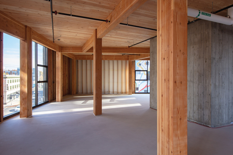
Figure 5. Interior shell awaiting tenancy.
Recesses were routed into the long sides of interior CLT panels to facilitate continuous 1-inch-thick plywood spline connections between panels. At Levels 3 and above, these splines, along with strategically-located steel strap connections in the orthogonal direction, allow the CLT panels to behave as a monolithic diaphragm in resisting lateral wind and seismic loads. CLT panel edges were further fabricated to allow for their connection along adjacent concrete walls.
The horizontal leg of a steel ledger angle is recessed into the underside of CLT panels by 1.5 inches, and screws between the ledger angle and panels facilitate the transfer of seismic loads between the CLT diaphragms and core walls. Tight-fitting wood filler blocks are used to fully conceal the ledger angles and protect them from a possible fire event. Where necessary, the transfer of seismic loads between CLT diaphragms and concrete shear walls is supplemented by horizontally oriented premanufactured hold-down hardware by Simpson Strong-Tie.
The structural design of Sideyard complies with the applicable provisions of the 2014 Oregon Structural Specialty Code (based on the 2012 International Building Code) and its reference documents, except that the use of the 2015 ANSI/AWC National Design Specification (NDS®) for Wood Construction was employed with the approval of the authority having jurisdiction. CLT was initially incorporated in the 2015 NDS. Floor vibrations were considered in accordance with the U.S. Edition of the 2013 Cross-Laminated Timber Manual by FP Innovations. CLT diaphragms at Levels 3 and above were designed in accordance with the 2015 white paper titled, Cross Laminated Timber – Horizontal Diaphragm Design Example, by Spickler, et al. RISA-3D was used for analytical modeling of the glued-laminated timber framing and Level 3 canopy, and ETABS for the analysis of the lateral force-resisting system. Revit was used for design coordination and drawing creation.
The use of mass timber in building construction is, of course, nothing new. Its recent renaissance is mostly due to a focus on sustainability and a desire to reinvigorate the lumber industry. This, in turn, has led to the fast-moving introduction of panel products and a host of premanufactured connectors. However, this speed of technological advancement is, in some cases, outpacing our understanding of related structural performance and the development of corresponding U.S.-based standards. For example, the development and implementation of standardized testing of premanufactured timber connectors are warranted. Despite a lack of approval from a nationally-recognized evaluation service like ICC or IAPMO, the Ricon-series timber connectors were approved for conditional use on the Sideyard project only by leveraging testing from a previous Portland-based project to demonstrate continued gravity load-carrying capacity when subjected to the maximum expected earthquake-induced rotation demands.
The renewed prevalence of mass timber buildings may also change how the structural engineering industry models and documents their designs. For example, given the hardware congestion typical at the intersections of mass timber beams and columns, BIM Level of Detail (LOD) 400 connection modeling, complete with screws and corresponding isometric views within the construction documents, may prove useful in mitigating potential constructability conflicts.
Sideyard has helped transform a neighborhood. At the same time, it serves as a case study of what is possible in mass timber construction and how the structural engineering community may navigate the design and documentation of such projects in the future.■
All photos courtesy of Stephen A. Miller.