
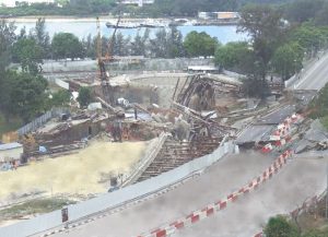
The Nicoll Highway excavation shoring construction collapse occurred in Singapore on April 20, 2004, around 3:30 pm. The accident deeply impacted Singapore’s local construction industry. Many regulations were tightened up through this incident, such as appointing qualified geotechnical engineers for deep excavation works and requiring authority submissions for temporary construction. The collapse resulted in four people killed and three injured. Several project parties were charged in court, and project completion was delayed.
Diaphragm walls with multiple levels of struts were often thought to be a robust earth-retaining wall system. How did such a system fail? This article revisits some of the contributing causes of the earth-retaining structure collapse and highlights six essential lessons learned from the incident.
Project Details
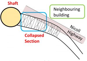
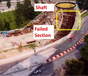
The collapse was located in the south-central part of Singapore island. The land transport agency of Singapore had wanted to build a circular metro line (Circle Line 1 Stage 1 – Contract C824) connecting the suburban areas of Singapore to the central business district in the downtown area. Excavation work for a cut-and-cover tunnel was underway and had almost reached the base of the excavation when the collapse occurred.
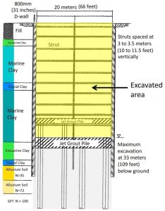
The 20-meter-wide (approximately 65.6 feet) cut-and-cover tunnel had to be constructed by excavating to 33 meters (approximately 108.3 feet) below ground level. The ground consisted of deep layers of soft marine clay with very low shear strength (20 kPa to 40 kPa), which typically increased linearly with depth. 800-millimeters-thick (approximately 2.6 feet) reinforced concrete diaphragm walls (D-walls) were used as earth-retaining structures, supported by 10 levels of steel struts, spaced at about 3 to 3.5 meters (approximately 9.8 to 11.5 feet) vertically. Two levels of Jet Grout Pile (JGP) near the base of the excavation were constructed to provide strength and stability to the soft soil as the base was being excavated. It is worth noting that such a deep excavation in adverse ground conditions would typically require a wall thickness of about 1500 millimeters (approximately 4.9 feet). That thickness is twice the size of the wall used in C824.
Modeling Undrained Behavior
In designing a multi-stage excavation, the use of software is often required. Although, in many cases, the drained behavior of soil is critical for excavation works (due to unloading), undrained behavior is still relevant and appropriate for soil such as marine clay, which has very low permeability.
The software used to design the cut-and-cover tunnel for Nicoll Highway was Plaxis. When considering the undrained behavior of soil, the relevant strength parameters are total stress soil parameters. For strength design, it is the undrained shear strength, cu. Designers may sometimes choose to input the value of undrained shear strength of a particular soil directly into the software. However, in Plaxis, the software allows the designer to model undrained behavior using effective stress parameters (i.e., using cohesion c´ and friction angle φ´). The advantage of this is that shear strength increase due to consolidation can be used in the design, resulting in economies. C824 designers took advantage of this and modeled the undrained conditions using effective stress parameters in Plaxis.
However, the C824 project designers failed to recognize that such an increase in shear strength can be quantitatively wrong, especially for soft clay. In a p-q plot, it can be visualized that in an undrained loading using the Mohr-Coulomb (MC) model, the stress path moves vertically upwards. This means that the center of the Mohr circle (p-coordinate) remains the same, while the radius of the circle (q-coordinate) increases. Note that p and q are also average stress (stress components added together and divided by the number of components) and deviatoric stress (difference in major and minor principal stress), respectively. In undrained loading, the load is taken entirely by the water in the soil, so there is no change in the soil’s effective stress. The load only increases the deviatoric stress (q-coordinate) as the Mohr circle becomes larger as loading increases. In reality, as the positive excess pore water pressure increases during undrained loading (i.e., pressure exerted on water), the stress path deviates to the left, resulting from a decrease in average effective stress (p-coordinate) because total stress = effective stress + pore pressure. As water exerts pressures in all directions, it is important to appreciate that an increase in vertical stress in water will result in the same stress exerted horizontally.
The over-prediction of soil shear strength using effective stress parameters resulted in severe under-design. The forces and moment in the retaining walls were grossly underestimated, and deflections predicted were too optimistic. This resulted in an earth retaining system that was inadequately sized. Back analysis for C824 D-walls showed that the bending moments and deflections were underestimated by 50%.
Curved Diaphragm Walls
The curved alignment on the metro line plan meant that the retaining walls had to follow this curvature. It should be noted that curved diaphragm walls posed many challenges for design and construction. First, the usual 2-dimensional (2-D) plane strain analysis adopted for a section design would not capture the effects of curvature, which runs in the out-of-plane direction. Forces and moments in retaining walls, strut forces, and wall deflections might be increased or decreased due to the curvature.
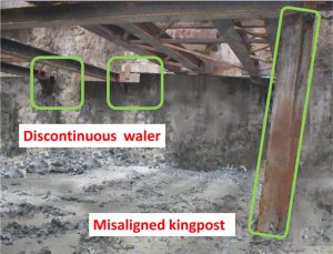
When it comes to construction, it is not easy to construct a continuous waler due to the wall’s curvature. In C824, discontinuous walers at some locations resulted in weakness between adjacent diaphragm wall panels. As D-walls were constructed as discrete panels, wall joints opened up at weak locations due to the lateral soil pressure acting in a direction causing the walls to move inwards into the excavation. A robust and continuous tying waler needed to be constructed to provide a “tying effect” to prevent opening up of the wall joints, which the designers had overlooked.
Utility Crossings
Existing underground utilities have to be protected from damage during excavation. Sometimes, utilities may be diverted away from the excavation area before construction commences, but this is not always possible. There will be occasions where project parties are required to contend with existing utilities in the way of the excavation activities. In C824, critical electrical cables (66kV) were in the way of the diaphragm walls. Utility gaps of 4 meters (approximately 13.1 feet) disrupted the continuity of the diaphragm walls. This created a zone of weakness in the diaphragm walls. In weak soils (e.g., loose sand and soft clay), soil loss occurred due to these weak soils leaking through the utility gaps at areas where the interfacing gaps were not adequately secured. Also, the builder had difficulties installing continuous strutting. For C824, investigators suspected that the jet grout piles (JGP) were not carried out near utility areas (due to concerns of damage), and this could have severely impaired the effectiveness of the JGP in providing strength when acting like a strut and providing stability close to the base of the excavation.
Poor Strutting System
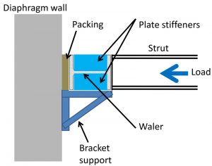
There were many inadequacies in the design of the strutting system in C824. Due to the design-and-build nature of the contract, the contractor wanted a very lean design. The curved diaphragm walls and close vertical spacing of the struts (obstructing ease of construction) did not help. In C824, it was found that some walers were discontinuous. Some struts were installed without splays. There were also cases where struts were bearing directly onto D-wall panels without a waler. The waler’s fundamental purpose was to provide continuous line support to the retaining wall so that loads could be redistributed, and the effects of eccentricity could be mitigated. When this was omitted, the effectiveness of the strutting support system was somewhat compromised.
Sway Stability of Open Stiffeners
During construction, it was found that some of the plate stiffeners for the strut and waler connection had buckled. The contractor thought that this happened due to more load being transferred through the strut’s flanges, resulting in the plate stiffeners being inadequate. Unknown to the contractor, the inadequacy of the steel stiffener plates was due to an overestimate of the stiff bearing length of the waler resulting in under design of stiffeners.
The contractor then replaced the steel plates with C-channels, thinking that the “bigger” C channel sections would perform better as stiffeners. This proved to be a costly mistake, as it was one of the main contributing factors leading to the strutting system’s inadequacy.
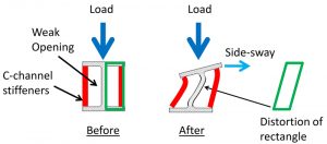
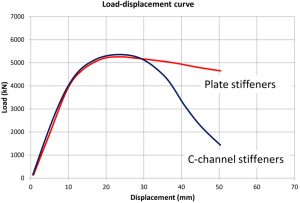
The contractor did not realize that the C-channels acting as stiffeners had resulted in an “open” stiffening system. This means that the “opening” created had an inherent weakness, a failure by sidesway. Sidesway failure mode is dangerous because of the after-peak brittle response. Once the system is overloaded beyond capacity, failure occurs suddenly and the load-carrying capacity decreases sharply.
Telltale Signs
A large-scale infrastructure project such as C824 inevitably required a large team of project personnel for design and on-site during construction. Despite the large team of engineers, supervisors, client representatives, and contractors present on-site, none of the project parties realized that the numerous abnormal sightings were telltales signs of an impending collapse. Before the collapse, the lateral wall deflection was more than 400 millimeters (approximately 1.3 feet), which did not appear to be alarming to the project parties. Furthermore, there were signs that the strutting system was under distress, manifested by stiffener plates buckling and kingposts deformed beyond vertical alignment.
The tragedy of the Nicoll Highway incident could have been avoided if project parties were aware of the dangers in deformed and distorted structural members and large wall and ground movements. In C824, the immense pressures of cost and time impelled the builder to take unnecessary risks, even to the extent of not stopping work in the face of warning signs, hoping to complete the work quickly so that the situation could turn around and stabilize. This mindset to rush work and complete the excavation and backfill to achieve safety is a dangerous fallacy. The more secure way would be to cease work and strengthen the weak areas to ensure safety and stability.
Comparison of Results
It is sometimes useful to check computer output using simple rules of thumb. Designers can use apparent wall pressure diagrams where lateral pressure pa acting on the wall = γH(1-m4cu/(γH)) to estimate the strut load. Using m = 0.4, cu = 30 kPa, γ = 18 kN/m3, H = 33m, pa works out to be 0.9 γH = 535 kN/m2. Adding a surcharge of 20 kPa (assume Ka = 1), the earth pressure becomes 555 kN/m2. Therefore, the estimated unfactored strut load is 555 multiplied by the spacing of 3.8 meters (largest tributary area near the base), giving 2100 kN/m. Designers should note that apparent earth pressures can only be used to estimate strut loads, not retaining wall forces.
To estimate retaining wall moments, designers can use Rankine’s earth pressure. Assuming active pressure is Kaσv and Ka = 1, with a surcharge of 20 kN/m2, maximum earth pressure is 33×18+20 = 620 kN/m2. The maximum bending moment is 620×4.52/8 = 1600 kNm/m using maximum bending moment for a simply supported beam (wL2/8). The factored moment becomes 1.5×1600 = 2400 kNm/m.
Using the above rule of thumb, designers must remember that these simplified methods cannot predict strut loads or wall forces with great accuracy, especially for a complex deep excavation project. It is only meant to give the designer a sense of the order of magnitude. This is because an actual excavation construction is a multi-stage process. Therefore, additional forces will be introduced during the intermediate stages of loading. Also, the stiffness and rigidity of the wall, struts, and soil interact with one another. Forces and moments get redistributed according to the soil and wall and strut movement. For example, a flexible wall bending moment would be very different from that of a rigid wall. Therefore, software such as Plaxis is often required to analyze a complex deep excavation project.
Conclusions
The safety of temporary construction might sometimes take a backseat because they are constructed only for a relatively short period to facilitate permanent construction. Parties are sometimes tempted to adopt lower safety standards for temporary works. However, this can be a costly mistake, especially for a large-scale project involving complex site conditions, as shown in the C824 incident. In Singapore, as a result of the C824 incident, temporary construction requires the same safety factors as permanent construction, and submission to authorities for approval of the design is required before work can commence on site.
Designers involved in complex geotechnical works need to understand soil behavior to use appropriate software and predict forces on retaining structures correctly, including the software’s assumptions and the limitations of the model and analysis results. In addition to theoretical knowledge, experience is also critical to identify site-specific problems and avoid potential pitfalls.■