
The Key to Mass Timber Construction
Part 2: Introduction to Glued-in Rods
This is the second part of the series of articles on modern wood fasteners. Part 1 (STRUCTURE, August 2020) focussed on self-tapping screws (STS). Part 2 introduces the reader to glued-in rods (GIR) and the components making up these joints. Part 3 will summarize design guidelines for the GIR connections. Despite the interest among designers of mass timber construction, there is no official recognition in U.S. and Canadian design codes for GIR connections. This article sheds light on the state of the art of this emerging technology. We caution the reader that this an area of development without code approvals in the U.S. and Canada – the content is provided as informational and not to be used for design.
As is the case for self-tapping screws, glued-in rod technology originates from Europe. Studies started in German-speaking countries and Scandinavia in the early 1970s, initially for repairing and reinforcing floor and roof structures. In the same period, pioneering research on inclined glued-in rods started in the USSR under the leadership of S.B. Turkovsky at the Central Research Institute of Building Construction (TsNIISK Kucherenko). In 1982, design rules for GIR connections were adopted in the Soviet timber design code and had remained active in the Russian building regulation. Using the Russian methodology, over a hundred projects of various sizes, with free spans up to 100 m (over 300 feet), have been completed in Russia (Figure 1).
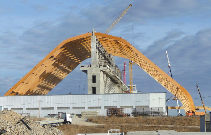
Figure 1. 85 m (280-foot) clear span frame in the Gremyachinsky mining and processing plant. Note that the center wall is not a vertical support. Courtesy of TSNIISK Kucherenko.
By the end of the 20th century, glued-in rods had been studied worldwide, including Canada, New Zealand, Australia, and Japan. To date, the basic rules for designing GIR joints have been adopted in timber design practice in Germany, Switzerland, Sweden, Italy, and New Zealand. Several proprietary systems have been approved in Europe for GIR joints. Attempts have been made to include the design rules for GIR joints in the international (CIB) and European (Eurocode 5) design codes, but no consensus has been reached yet.
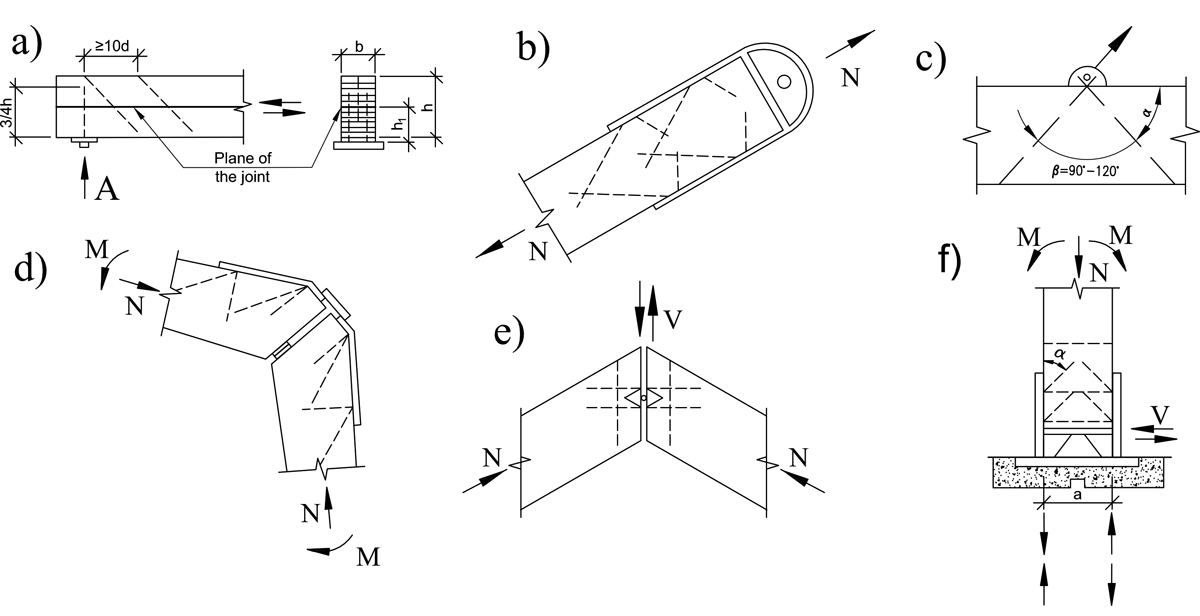
Figure 2. Applications of inclined glued-in rods. a) connections of built-up members, b) members in tension, c) lifting lug anchorage, d) rigid knee joint, e) ridge connection, f) column fixed base reinforcement. Dashed lines are GIR’s. Recreated from TsNIISK Kucherenko.
The principles and applications of GIR joints are somewhat similar to those of self-tapping screws. Steel rods with profiled shanks (threaded or ribbed) are embedded deeply into timber. The rods are preferably loaded axially to provide superior stiffness and strength for transferring forces and/or moments at joints or reinforce timber near supports and in zones of high horizontal shear or tension perpendicular to the grain (Figure 2). Depending on the design configuration, the load-bearing capacity of the joints may be governed by the pull-out resistance of the bondline or by the resistance of the steel shank of the fastener. Therefore, a higher capacity may be achieved with fewer glued-in rods than with screws. Using milder steel rods of smaller diameters may be desirable to achieve ductile performance of the joints. With careful choice of diameter and spacing of the rods, highly efficient joints can be designed with minimum loss of stiffness and strength of the adjoining members, even for loads of 400 kN (90 kips), as illustrated in Figure 3.
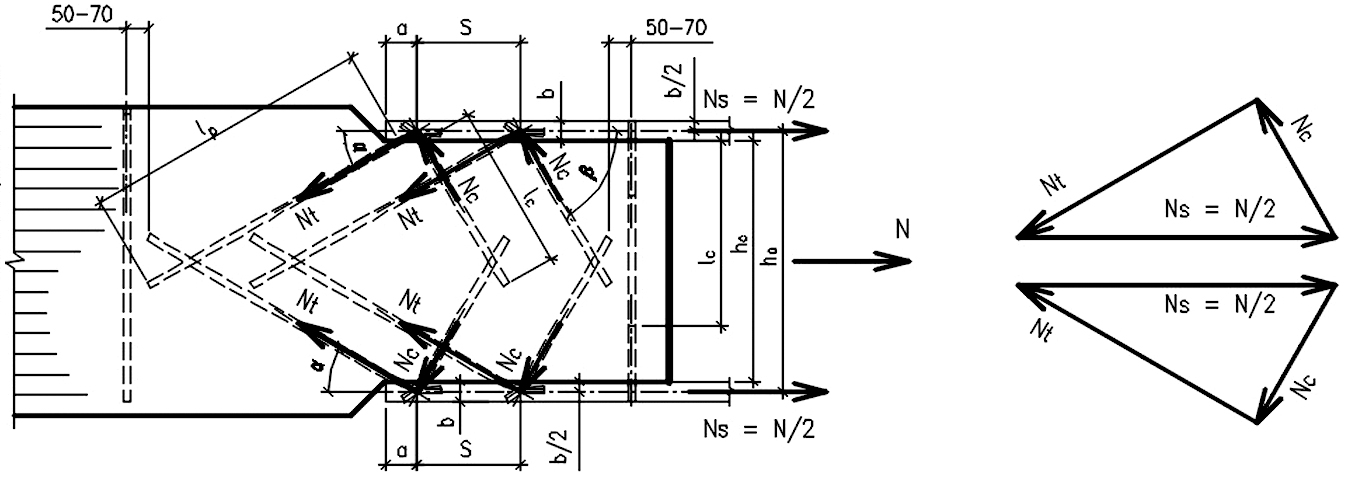
Figure 3. High-capacity GIR joint with 400 kN (90 kips) capacity using inclined GIR welded to steel flange plates. Transverse GIR is for joint reinforcement. Courtesy of TSNIISK Kucherenko.
Furthermore, the design resistance of timber members can be significantly enhanced with transverse reinforcement against splitting and shear. These are desirable features for engineers and architects who want aesthetically pleasing, versatile, 3-D structures with benefits for long-span structures, high fire resistance, or protection against corrosion.
While STS may not often need pre-drilling and can be quickly and easily installed in-situ with minimum precautions (avoiding over-driving and breaking the screws), glued-in rods require carefully controlled fabrication procedures, normally in a factory setting. As opposed to the STS, where the fastener’s threads are directly engaged in mechanical grip with wood, the bond between the glued-in rod and wood is created utilizing an adhesive that forms a composite system (Figure 4). Consequently, each rod’s pull-out resistance greatly depends on the quality and durability of the bond between the rod and the adhesive, between the adhesive and the wood substrate, and, obviously, on the adhesive itself.
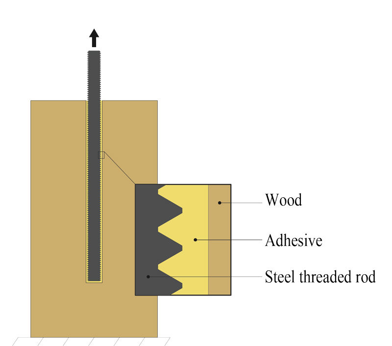
Figure 4. Glued-in rod composite system. Courtesy of Raphaël Bouchard.
Numerous studies have investigated various adhesives, bondline thickness and length, rod materials and diameters, wood grain orientation, heat and moisture resistance, creep, etc. Phenol-Resorcinol-Formaldehyde (PRF) has been found unsuitable for GIR applications because of significant shrinkage and brittleness. Adhesives that have been approved for GIR are two-component polyurethanes and epoxies. Epoxies provide stiffer bondlines, which may or may not be advantageous for the GIR joint performance, given stiffness compatibility with the wood substrate. Considering that Young’s modulus of wood is 20 to 30 times higher along the grain than in transverse direction, the distribution of stresses along the bondline and resistance and long-term performance depend significantly on the angle of insertion of the rod and loading direction. Design and fabrication of GIR connections require sound knowledge and understanding of materials involved in this composite system to avoid dramatic mistakes. Basic guidelines are discussed below.
Design and Production Guidelines
Materials
Glued-in rods can be used with glulam, LVL, CLT, and solid wood panels. Applications in softwood glulam timber are the most frequent today. Since CLT panels have gained momentum worldwide, efficient and reliable connections are often sought, especially for multi-story buildings. The fabrication and performance of GIR joints in CLT is an area of current study underway at Laval University in Quebec City, Quebec. If CLT is produced without edge-gluing of laminations, which is predominantly the case in the U.S. and Canada, special measures to avoid leakage of adhesive in the gaps between laminations are needed. The leaks lead to “starving” bondlines where the adhesive is poured into a “bottomless” hole and does not surround the rod properly. Therefore, European approvals of GIR joints are only valid for the CLT made of edge-glued and ungrooved laminations. There are also special restrictions on positioning the rods within CLT laminations and the penetration length that must be followed until more research data becomes available.
Rods
Threaded rods of low and medium carbon steel with yield strengths between 250 and 380 MPa (36 ksi to 55 ksi), such as ASTM 1554 Grades 36 and 55, are currently recommended. The lower strength allows designers to rely on rod yielding as the governing failure mode, which provides more predictable resistance independent of load duration effects. Furthermore, in cases such as seismic design, where it is necessary to avoid brittle failures, the performance of GIR joints should be limited by yielding of the rods. To ensure that rod yielding governs the design, extra bonded length is provided for capacity protection because the maximum ultimate strength of the steel is higher and may control. Overstrength factors between 1.2 and 2.1 have been proposed in the literature. It is currently proposed that the design capacity of the bondline should be at least 50% greater than the design capacity of the rods.
Figure 5. Concept of a glulam portal frame connection using steel threaded glued-in rods with a steel connector weldment to allow bolted assembly onsite. Threaded rods must be glued in factory conditions. Adapted by Raphaël Bouchard from Buchanan and Fairweather (1993).
When the design resistance of the joint is governed by the rods, the design is essentially a steel connection familiar to most designers. Threaded rods are easily connected to other steel parts using nuts (Figure 5). Alternatively, ribbed reinforcing steel bars (rebar) present a very economical option. In construction joints, rebar can be welded to other steel parts (as shown in Figure 3), with certain precautions to avoid burning the wood. In welded joints, the portion of the bonded length within 3 diameters of the rod near the weld should be discounted because of overheating.
Figure 6. The approximate behavior of GIR showing axial yielding of rods with sufficient bonded length.
Rods with diameters from 8 mm (5⁄16 inch) to 30 mm (13⁄16 inch) have been tested in GIR connections. The most practical range of diameters is between 12.5 mm (½ inch) and 20 mm (¾ inch). The bonded length considered in design with softwood timber products is between 10 and 30 times the nominal rod diameter. Smaller diameters and shorter rods are impractical and can be easily replaced by screws. Longer rods may be used when necessary to avoid stress concentrations, but length does not necessarily increase the joint’s resistance in softwood timber products (Figure 6). More work is required to develop design methods to account for the broad range of bonded lengths. Note also that drilling deep and large holes requires dedicated equipment that most producers do not possess.
Hole Diameters
Some earlier studies focused on holes with smaller diameters, sometimes smaller than the nominal diameter of the thread, aiming at mechanical locking of the threads with wood and economical use of adhesive. It has been established that the thickness of the bondline does not significantly affect the joint’s performance. However, the oversize of the hole does affect the ease and accuracy of installation and the amount of adhesive used. Currently, recommended hole diameters are between 2 mm (1⁄16 inch) and 6 mm (¼ inch) larger than the rod diameter. Holes of smaller diameters are not recommended.
Adhesives
In Europe, several manufacturers obtained their own National Technical Assessment (NTA) and European Technical Assessment (ETA) reports on adhesives for bonding steel rods into wood building materials using either two-component polyurethanes or epoxies. Typically included in these reports are basic information on the adhesive properties, installation instructions, and specific design parameters, such as characteristic pull-out strength as a function of the bondline thickness and length, recommended minimum spacing, and limits of the bonded-in length of the rods. In all cases, the installation must be executed by specially trained authorized personnel in a controlled environment.
Joint assembly
Because of the very high stiffness of GIR joints, there is little redistribution of forces between the rods until they start yielding. Therefore, nuts should be tightened uniformly using a torque-limiting wrench to close any initial gaps in the joints during the installation and induce equal tensile forces in the rods. A study conducted by R. Bouchard at Laval University showed that a torque of 75 N.m (55 lb.ft) is sufficient to achieve the desired effect. Overtightening (snug-tight installation) may be harmful to the joint performance because overtightening may cause excessive prestressing of the bond line. Prestressing is not recommended for low carbon steel.
Quality Control (Q.C.)
Thorough quality control is a key in the GIR technology, especially when the structure’s integrity relies upon high-capacity rigid joints. As in any gluing process, the components’ surface preparation is of primary importance: the rods and holes in timber must be clean and dry, free of rust, grease, and dust. It is essential to avoid overheating the wood when drilling the holes.
The timing of the gluing operations and the ambient and surface temperature must be within limits imposed by the adhesive supplier. Any deviation from the prescribed procedures may compromise the bond’s quality and put the finished structure at risk of catastrophic failure. Since the glued joints are hidden inside the wood, visual inspection is difficult. Unless elaborate (and expensive) NDT techniques are employed, the bond’s true quality remains uncertain. At a minimum, the quality of the cured adhesive should be tested for every batch during fabrication according to a Q.C. plan.■
References
SP 382.1325800.2017 Glulam timber structures with bonded-in rods: Design methods. Ministry of Construction, Russia. Moscow.
Bouchard, R. Longitudinal Tensile Behavior of Joints with Multiple Glued-in Rods in Glued-Laminated Timber. Master’s Thesis in Wood Science, Laval University. Québec, Canada, 2020.
Fabris, Alessandro Fabrizio. Improvement of the Tensile Properties of Construction Timber Parallel to the Grain by Means of a Bond with Profiled Steel Bars. Doctoral Thesis, ETH Zurich, Switzerland, 2001. https://doi.org/10.3929/ethz-a-004130046.
Tlustochowicz, G., E. Serrano, and R. Steiger. 2011. “State-of-the-Art Review on Timber Connections with Glued-in Steel Rods.” Materials and Structures 44 (5): 997-1020.
Seismic Design of Glulam Structures. A.H. Buchanan and R.H. Fairweather. Bulletin of New Zealand Society for Earthquake Engineering, 24(4):415-436. 1993.