
5 Factors for Joist and Deck Specification
The growth of e-commerce has bolstered warehouse and distribution center construction, with new project starts forecast to increase in 2021. Here are 5 areas where collaboration between the specifying engineer and the joist/deck supplier improves construction efficiency, shortens project timelines, and reduces total project costs.
RTU Loads
Often, the structural drawings for a warehouse will only generally indicate the presence of a rooftop unit (RTU) on the roof plan. Not specified is the unit’s distance to a column line or the end of a joist. This information is not often known at the time the Design Drawings are released for bidding or construction. Whatever the reason, the lack of specificity about the location of mechanical equipment will trigger a request for information (RFI) cycle. The joists cannot be engineered and manufactured until the specification is made clear. To avoid this delay, the project engineer has options.
Option A: Specify General Location
Suppose you know that the RTU will be located within the first 10 feet along the length of a particular joist. In that case, this is usually enough information for the joist manufacturer to proceed. Joist estimators and engineers know to strengthen the joist to support the RTU placement at any panel point along that 10-foot section of the joist. The additional cost for material is nominal compared with an exactly located unit within that zone, and far offset by the expediency of keeping the project moving.
Option B: Specify a KCS Joist
KCS-Series joists are modified K-Series joists built to address constant shear and moment resulting from gravity loads along their spans. KCS joists are designed for compression in the top chord and tension in the bottom chord, and constant positive and negative shear in the web members, to account for varying load locations and potential stress reversals no matter where shear may occur within the joist. All web members, except the end diagonal webs of a KCS joist, are engineered to resist 100% of the published shear capacity applied in tension or compression. The result is a very strong joist engineered to support RTU and other mechanical loads at any panel point along the joist. KCS-Series joists are ideal for warehouses with multiple loads by way of conveyors, catwalks, and suspended processing equipment. The cost of a joist will be higher due to the increased steel content. But, in addition to the avoidance of prolonged RFI’s and potential project delays, the specification of KCS-Series joists gives the building owner the flexibility to, at a later date, add or move loads along the joist span.
Expansion Joints
For larger warehouses, expansion joints, sometimes called “slip joints,” allow for thermally induced horizontal shifting of a large section of roof joist girders, joists, and steel deck relative to another section. For expansion joints to perform properly, the specifying engineer must allow for adequate seat depths at the slide bearing locations. Doing so will permit the differential movement between the adjoining roof areas.
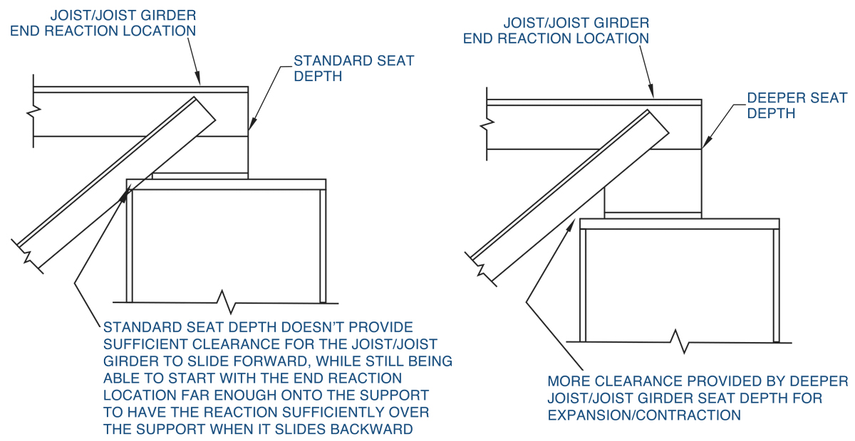
Figure 1. Expansion joints.
Allow for Joist Seat Depth
As shown in Figure 1, if the joist seat depth is too shallow, the diagonal end web of the sliding joist girder will be impeded by the column cap plate, with the risk of structural damage during thermal movement. Given the proper joist girder seat depth, the joist engineer can address the full range of anticipated thermally induced horizontal movements at each expansion joint. The Steel Joist Institute’s (SJI) Standard Specification 100-2015, Table 5.4-3, can be used to determine the minimum seat depth required to accommodate the anticipated amount of slip. The minimum “RP” value to use in the table equations should equal the sum of anticipated forward and backward slip amounts, plus:
- ½ inch for K-Series joists,
- 2 inches for all LH-Series, DLH10-17, and joist girders with a self-weight ≤ 50 plf,
- 4 inches for all DLH18-25 and joist girders with a self-weight > 50 plf.
So, a joist girder weighing 60 plf, requiring +/- 1.75-inch slip, requires a minimum “RP” value of (1.75-inch x 2) + 4 inches = 7.5 inches. Entering Table 5.4-3 with RP = 7.5 inches results in a minimum seat depth, D:
D = RP + 4 inches (for joist girders)
D = 7.5 inches + 4 inches
D = 11.5 inches (round up to 12 inches)
Tilt-Up Walls
Tilt-up walls are frequently used on warehouse projects for efficient construction, but the expedience gained will be diminished when dimensional considerations related to the steel joists and roof decking are not clearly called out in the structural drawings.
Wall Thickness
Concrete tilt-up walls are first poured as horizontal slabs to create panels. Each panel is typically fabricated with embedded steel plates to support and attach the steel joists and/or joist girders. The panels are poured on-site and tilted vertically to establish the warehouse walls. The steel joists and joist girders are soon added to tie the structure together; but, for the joists to properly fit-up with the tilt walls, the joist engineer needs to know the wall thickness. Wall thickness dimensions are sometimes completely missing from the structural drawings. Other times, the dimensions are only partly indicated, such as when walls with varying thicknesses are not clearly called out or when panels that have reveals are not clearly detailed. But, as shown in Figure 2, when these dimensions are clearly detailed in the structural drawings, accounting for any variations, no related time is lost in the engineering of the joists.
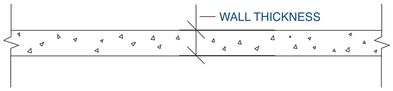
Figure 2. Wall thickness.
Account for Jogs
Tilt-up walls sometimes have “jogs,” at which point two panels lap or offset each other to create a jog in the face of the panels. The structural drawings frequently do not indicate the dimensions for these offsets, including the “gap.” But when these dimensions are called out, as shown in Figure 3, the joist engineer loses no time determining the exact length of the joists. Manufacturing can be underway, and the joist detailer can include precise details to the erector for the proper fit-up of the joists on-site.
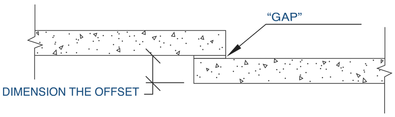
Figure 3. Account for jogs.
Show Wall Location
Typically, one face of the wall, inside or outside, will be located relative to the adjacent column centerline. This information needs to be called out in the structural drawings, as shown in Figure 4, regardless of which face of the panel is dimensioned. Dimensions to the inside face of the wall are the most critical for joist length. When the tilt panel’s inside face is dimensioned from the adjacent column centerline, changes in panel thickness made by the precast contractor during their design will not affect the joist or joist girder lengths. This helps avoid length discrepancies that are costly both financially and to the erection schedule. It also helps avoid RFI delays when uncertainty exists related to panel thicknesses or wall face locations.
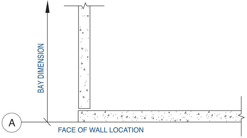
Figure 4. Wall location.
Note the Bearing Conditions
The clear specification of the bearing conditions for the joist and joist girder connections to the tilt-up walls will avoid costly connection issues. Connections include members bearing on a precast haunch on the wall face, in a wall pocket, on the face of the wall with an embedded plate shear connection, or on a steel embed angle on the face of the wall. Leaving these connections unknown will predictably delay the project schedule and increase the potential for coordination issues.
Uplift Forces
Show Net Uplift
RFI delays can be avoided by clearly specifying the uplift per the factors shown in Figure 5: A) Indicate the wind uplift pressures required for the design of the steel joists and joist girders separately; B) Indicate whether wind uplift is net or gross; C) State whether the wind uplift values were determined using LRFD or ASD load combinations. Unless the structural drawings specifically state the joists are to be designed using LRFD or ASD, the joist manufacturer may use either. It is helpful for the structural drawings to include a note indicating the roof dead load used to calculate the net wind uplift, in case the manufacturer needs to convert from LRFD net pressure to ASD, or vice versa. Generally, the full design dead load is not used to determine the design net wind uplift, since that dead load includes allowances for equipment and other incidental loads that may not be present at all areas of the roof or for the life of the building. Net uplift pressures on warehouse projects are typically specified using service level (ASD) net uplift, but the joist engineer cannot assume this. An incorrect assumption can lead to over-design, or even worse, an under-designed joist and joist girder system.
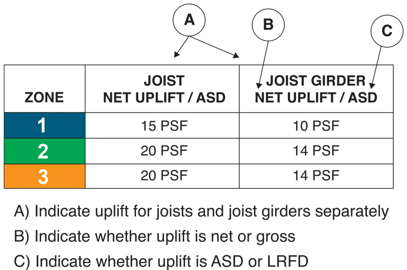
Figure 5. Uplift forces.
Show Uplift Zones
If the uplift values are given for different “zones” (i.e., interior, perimeter, corner), then a diagram of the zones, including the dimensioned widths of each zone, must be provided on the structural drawings, as shown in Figure 6. Do not simply show an undefined “a” dimension, as it is a code level determination that should be made by the specifying engineer while specifying the uplift.
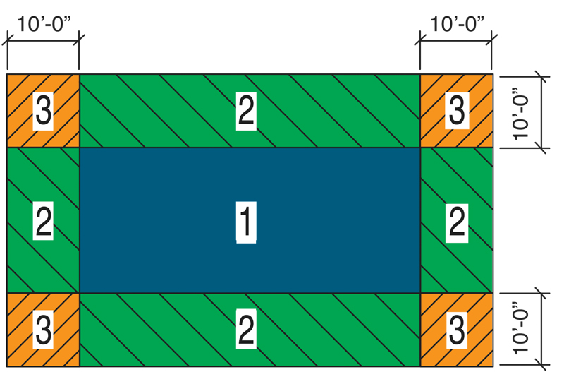
Figure 6. Uplift zones.
Project Sequencing
Efficient joist and deck sequencing go hand-in-hand with efficient warehouse construction.
The authors recently participated in a large project initially specified to have 126 sequences. By collaborating early with the specifying engineer and erector, the sequences were reduced to 18. On another project, multiple cranes operating simultaneously were aligned with joist and deck sequencing to opposite ends of the building, thus keeping two erection crews moving efficiently toward the middle. And, as happens on projects when the sequencing of a warehouse changes, it is relatively easy to adjust – provided the organized joist and deck sections do not change (e.g., SEQ 1 = column lines 1-8).
Too often, this is not how it goes, as many erectors can report. Without a clear sequencing plan upfront, the joists and deck will arrive in bulk. The erector will lose time shaking out each truck, sorting and transporting the correct pieces to the appropriate locations of the building. Sequencing can also be disrupted by decisions made late, after the joist drawings are submitted for approval. A GC may change the sequencing to satisfy the precast company’s request to deliver the walls batched to match the tilt-up schedule. Or the erector may decide late that the joists, decking, and bridging for a high roof should be delivered first, having realized late that there was not enough lay-down room on-site for the entire joist order.
When these changes to earlier planned sequencing occur, joist and deck delivery time is disrupted. Pieces must be manually pulled, re-organized, and re-identified. The disruption also impacts other project stakeholders, including the owner, as re-sequencing elevates the potential for material supply errors, inefficient erection, delayed occupancy, and lost revenue.
Conclusion
For many larger warehouse projects, the steel joists, joist girders, and decking comprise a significant percentage of the structural material. The most frequent constraints to successful project delivery, related to joist and deck, are well known and documented in this article. Early collaboration among the supplier, specifying engineer, erector, and GC to address these constraints will prevent confusion, project delays, unnecessary costs, and assure the building owner the earliest possible occupancy.■