
Reconnecting Communities through Creative Infrastructure
The recently constructed Beehive Bridge in New Britain, Connecticut, and winner of the American Council of Engineering Companies (ACEC) Engineering Excellence National Merit Award, is a testament to the power of structures to connect people and connect to people. The Beehive Bridge reconnects long-divided neighborhoods, encourages pedestrian use, and represents its community through its singular design (Figure 1).

Figure 1. Beehive Bridge elevation.
A Community Divided
When State Route 72 was installed through the center of New Britain in the late 1970s, rapid access to the adjacent interstate system was the driving force behind the construction. At that time, the fact that the sunken roadway ran straight through the middle of the city was a secondary concern. Though several bridges were installed to reconnect the now separate neighborhoods, connectivity to the downtown areas was irrevocably damaged. People found it more convenient to avoid the bridges and stay on their side of the highway. The result was a city divided by a highway installed to serve it.
Merging Form and Function
In visualizing a fix to this long-standing condition, New Britain Mayor Erin Stewart initially planned to incorporate public art into one of the Route 72 overpasses to create a public space that would draw people to cross the highway and shelter them from the highway bustle and noise. To help realize this vision, the City hired a design team led by engineering firm Fuss and O’Neill of Manchester, CT, along with design team members Svigals + Partners, Pirie Associates, and Richter & Cegan, Inc. The actualized design takes inspiration from the City’s seal, which includes bees, a beehive, and the motto in Latin of “industry fills the hive and enjoys the honey” that pays homage to the City’s industrial past.
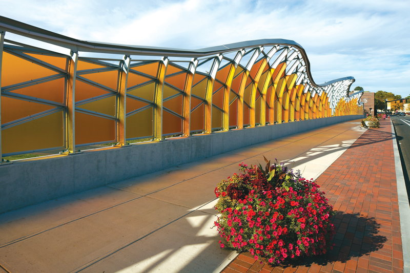
Figure 2. Pedestrian view from the sidewalk at day.
The unique focal point of the project is the pedestrian enclosure, which consists of more than 2,100 amber-honey-colored, ½-inch-thick polycarbonate panels arranged in the shape of a giant honeycomb. Its unique appearance shines as a landmark for the City and changes the landscape throughout the day. During daylight hours, the enclosure paints the bridge in ever-changing shades as the sun moves through the sky (Figure 2). At night, programmable LED lighting creates a 21st-century beacon inviting travelers to the City (Figure 3).
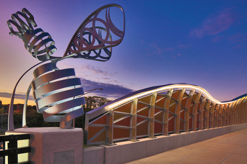
Figure 3. Bee sculpture watching over the structure at dusk.
Transformation
The existing bridge carries Main Street over Route 72. The bridge is 270 feet long, split evenly over two 135-foot spans. It is a typical overpass from its time, consisting of 10 haunched steel plate girders supporting a composite concrete deck. Before the redesign, the bridge carried 5 lanes of traffic and had two 10-foot-wide concrete sidewalks on either side, for a total out-to-out width of 86 feet 6 inches.

Figure 4. Approach to the bridge showing widened sidewalks.
In its finished state, the bridge has undergone a road diet to favor pedestrian foot traffic over vehicular traffic. While the out-to-out width remained unchanged, each sidewalk was expanded from 10 feet wide to as much as 21 feet wide. The sidewalks were edged with a 5-foot-wide brick paver strip embedded in the concrete adjacent to granite curbs. Traffic lanes were reduced to three lanes plus two new bicycle lanes. As part of the artwork, the larger of the two sidewalks has a giant aluminum beehive sculpture on a raised dais. At each of the four corners of the bridge, 11-foot-tall aluminum bees greet travelers to their hive from their vantage point on raised plinths tied to the concrete abutments (Figure 4).
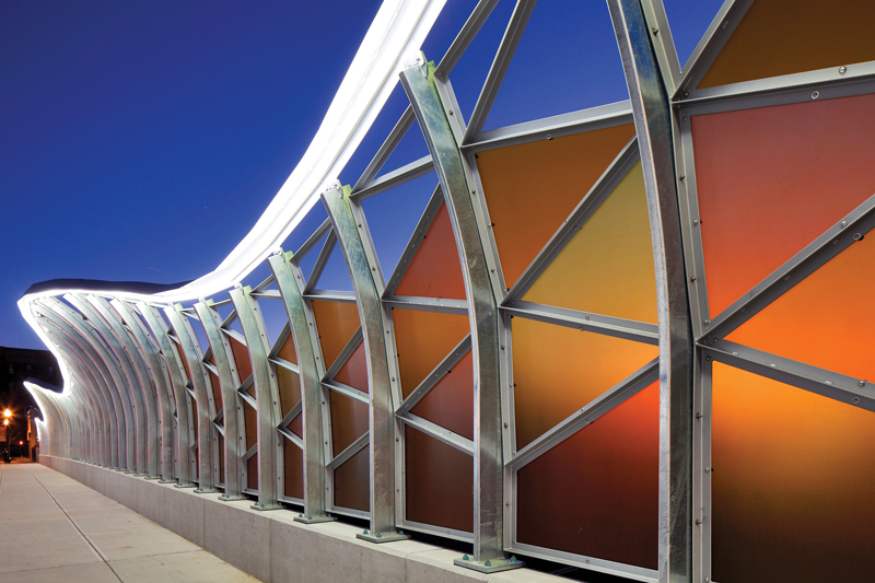
Figure 5. Closeup of beehive lattice at dusk.
The spine of the pedestrian enclosure is made up of 138 individual 6-inch x 2-inch x 1⁄4-inch-thick galvanized structural steel tubes evenly spaced at 4 feet on-center. The posts form the rough outline of the pedestrian enclosure shape, with each post varying in length between 3 feet 4 inches to 7 feet 8 inches tall. The posts are all bent inward towards the sidewalks, starting at the same inflection point, creating symmetry at eye level. As the post lengths vary, the end of the frame terminates at different points overhead, creating a dynamic curving and swooping envelope that undulates gradually overhead as one walks from one end of the bridge to the other (Figure 5).
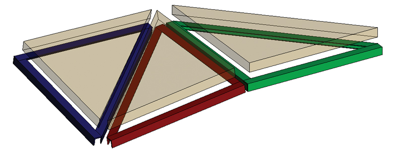
Figure 6. Schematic of panel connections. Each flat piece of polycarbonate panel (transparent) needs a single co-planar aluminum frame (multicolor) to support it. The frames connect at the edges.
Between the steel-post spine is a lattice network of aluminum members arranged into geometric shapes (mostly triangles, with a few quadrilaterals) to support each edge of every half-inch polycarbonate panel (Figure 6). The legs of this lattice consist of a structural angle with a third aluminum fin welded onto it, making a lopsided “T.” The fins were individually measured and custom-welded to control the angle of the fin to the aluminum angle base. This was necessary because each of the three sides of every polycarbonate support frame, made up by three separate aluminum “Ts,” need to be co-planer to flush-mount cleanly behind each piece of polycarbonate. Most of the aluminum frame members support two separate polycarbonate panels, one panel resting along one leg of the main structural angle, and another adjacent piece of polycarbonate along the aluminum fin. Each leg of the support needs to be bent at a slightly different angle to work as a system, with matching sides of the members under the same piece of polycarbonate being always co-planar, while also following the geometry established by the posts of the installation (Figure 5). Significant parametric computer modeling, prototyping, field coordination, and shop work was needed to accomplish this geometric jigsaw. It was imperative to ensure that the panels would each have their required edge supports while still keeping bolt holes within tolerances, both at the polycarbonate panels and the connection points along the spine.
The bridge is skewed 18 degrees out of perpendicular to the roadway below it and is built along a vertical highway curve, which adds to the geometric complexity of the enclosure. This was a design challenge because, though the two parapets match the vertical curve at the same given point along the highway baseline due to the skew of the bridge, the two pedestrian enclosures on either parapet start and stop at different points along the curve. The net result for fabrication was that no two panels of the bridge were precisely alike. In essence, each panel piece (all 137 panels between the 138 posts) had to be custom manufactured horizontally and vertically to properly fit its exact spot on the bridge deck.
Creation
Structurally, the pedestrian enclosure had to be designed for the American Association of State Highway Transportation Officials (AASHTO) Bridge Design Guide’s prescribed loadings, including wind, ice, snow, standard pedestrian loadings, and thermal expansion. Geometry from the architect’s computer model was adjusted to account for the latest measurements of the bridge’s existing shape. The model was fed directly into the structural engineer’s finite element analysis software to confirm the frame’s ability to withstand the required loading. The polycarbonate panels were checked against a wind- and vandalism-type impact loading. Thermal movements were designed to be dissipated over the numerous oversized bolted connections throughout the structure’s lattice.
The pedestrian enclosure was built on top of reconstructed concrete parapets that were fastened to the existing deck with drilled and epoxied steel dowels. The parapets were built lower than standard to bring the bottom half of the pedestrian enclosure’s shape to eye level and built wider to support the full width of the base plates of the enclosure’s posts. They also conceal several embedded conduits that feed the LED lighting scattered throughout the structure. Paraffin joints, traditional parapet contraction joints coated with paraffin wax, were deliberately spaced to match up with scoring lines in the sidewalk to help blend them into the overall aesthetic.
The City’s desire for real brick pavers embedded into the concrete deck to match the streetscape on the approaches was unusual for a bridge. The design team accomplished installation by deepening the notch for the bricks to include a drainage mat at the bottom. This mat is rated for pedestrian and tire loads, and is pitched to deposit water out of the paver notch and toward one of several scupper downspouts on the structure.
A Community Reunited
The seals on one end of the bridge proudly state, “Do the Impossible.” The public, press, and civic leaders have recognized this project as the significant innovation that it is. The ribbon-cutting ceremony was a huge event, bringing together the project team, City officials, project stakeholders, community groups, families, the press, and residents. The Connecticut Main Street Center advocated and contributed early financing for transit-oriented development in the area. Under construction is Columbus Commons, a $58M mixed-use transit-oriented development with 160 new apartment units, which is a short walk from the Beehive Bridge. City leaders have pointed at an uptick in commercial and residential activity in both of the previously divided neighborhoods, and they anticipate future returns on their investment. The Beehive Bridge is truly a community showpiece that fosters both its people and its infrastructure.■