
Development, Achievements, and Possibilities
Cable-stayed structures are the youngest, fastest-developing, and most promising bridge systems.
Cable-stayed bridges are a subcategory of suspended structures. A cable-stayed bridge is similar to a suspension bridge in having towers and a deck-girder supported by cables; however, its diagonal cables transfer the vertical loads from the deck directly to the towers. Thus, the main deck-girder of a cable-stayed bridge works like a continuous beam on cable supports (more flexible than pier supports) with additional compression force throughout the deck. A cable-stayed bridge is also a prestressed system as its cable-stays are additionally tensioned to counterbalance a significant part of the vertical loads on the main deck-girder.
The Strömsund Bridge in Sweden, completed in 1956 with a 182-meter (597-foot) main span, is considered the first modern cable-stayed bridge. For the following 65 years, cable-stayed bridges have seen a dramatic increase in both the number of new structures and in long-span achievements. By 1995, there were only 3 cable-stayed bridges with spans over 500 meters (1,640 feet); 25 years later, there are already 67 cable-stayed bridges with spans over 500 meters (including three over 1,000 meters or 3,280 feet). Another 29 with spans over 500 meters, with some over 800 meters (2,624 feet), are currently under construction.
The efficient range of cable-stayed bridges is moving towards even longer spans. There is no other bridge structural system exhibiting such rapid development. Most cable-stayed bridges are visually beautiful, and some are among the most impressive of engineering achievements.
Origins and Precedents
The idea for the cable-stayed system was perhaps inspired by the drawbridges of medieval castles and the rope-braced masts of tall ships. The very first documented image of a cable-stayed bridge appears in the Machinae Novae, a book by Fausto Veranzio published in 1615.
Predecessors for modern cable-stayed bridges appeared in the 19th century in the form of different hybrid combinations of suspension systems with additional diagonal straight cables, as in the case of the Albert Bridge, UK (1873). The best known of these hybrid structures is the Brooklyn Bridge, New York, 1883, with a 486-meter main span (1,594 feet), for which John Roebling used diagonal cables for stiffening the structure.
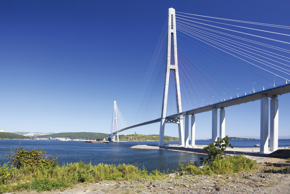
Figure 1. Russky Island Bridge.
In the 1960s and 1970s, the system was developed further to replace many of the bridges destroyed in Germany during World War II. In this period, the system was also used for roof structures requiring long, column-free spaces in buildings. Initially, cable-stayed structures were used for bridge spans of 60 to 250 meters (196 to 820 feet) but today they span much longer distances and are the only system that challenges suspension bridges in super-long spans. Their spans grew to 302 meters (990 feet) in 1959 with the Severin Bridge (Germany), to 404 meters (1,325 feet) in 1974 with the Saint Nazaire Bridge (France), and 856 meters (2,808 feet) in 1995 with Michel Virlogeux’s Normandy Bridge (France). Today, the Russky Island Bridge (Russia) has the longest span of this system, 1,104 meters (3,622 feet) achieved in 2012 (Figure 1).
In the United States, we can mention the second Sunshine Skyway Bridge with a span 366-meter (1,200 feet) in 1987 (Florida), the Dames Point Bridge with a 396-meter span (1,300-foot) in Florida, and the Arthur Ravenel Bridge with a 471-meter span (1,545-foot) in 2005 (South Carolina).
System Specifics
The main elements of a cable-stayed bridge are towers or pylons, deck girder(s), cable-stays, anchorages, and foundations. Tower and pylon are interchangeable terms; lighter, slender towers are often called pylons. The classic cable-stayed bridges are symmetric with one central span, two side spans, and two towers; such are most cable-stayed bridges with spans above 600 meters. The back-up cables may extend over several side spans.
Asymmetric cable-stayed bridges have one main span and one side span, with a single tower. Multiple-span cable-stayed bridges have two or more (usually equal) main spans. Several examples are shown in Figure 2.
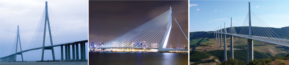
Figure 2. Span options: main with two sides spans, asymmetric and multi-span.
Some sub-divisions are used for cable-stayed bridges: extradosed, under-spanned (under-deck), cradle, inverted Fink truss, and tensegrity. The cables at the towers can be arranged in parallel (harp), fan, star, or mixed configuration. Various structural solutions are used for the towers: single pylons, double-leg portals (vertical, slightly angled, free-standing, or interconnected as a portal frame, with “A,” “H,” “Y,” or inverted “Y” shaped arches).
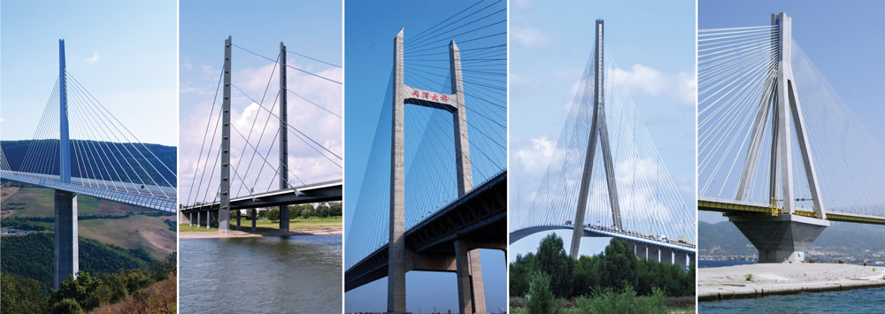
Figure 3. Tower configuration options.
The towers can be continuous above and below the deck supporting both the deck and the cables, or the upper part can support only the cables while the deck-girder is supported directly by piers. Examples are shown in Figure 3.
The primary construction materials used in cable-stayed bridges are:
- For decks: reinforced or prestressed concrete, composite concrete-steel, or orthotropic steel decks;
- For deck-girders: beams of prestressed concrete or steel, box girders of prestressed concrete or steel, similar to those in modern suspension bridges;
- For towers: steel, reinforced or prestressed concrete, composite steel-concrete;
- For cables: high-strength steel wires, usually 270 grade (270 ksi, or 1,860 MPa), built from 7-wire, ⅜-inch (9.5 millimeters) strands per ASTM A886, other higher-grade steel wires, carbon fiber-reinforced polymers (CFRP), or composites. Prestressed concrete has been used in the past, but should be avoided as it has been proven unsafe on some failures such as the Morandi Bridge;
- For piers and foundations: reinforced concrete with or without piles depending on the soil.
For long-span bridges, foundations on soft soils, or for bridges in high seismic areas, it is preferable to use predominantly steel structures to reduce the self-weight and the related earthquake forces.
Conceptual Design
The most important part of bridge design is the overall concept for the structure and its elements: the selection of the appropriate structural system for the bridge considering its specific function, site location, and required spans. A well-selected concept determines the efficiency and economy of the bridge, saves materials, cost, and construction time. Good design concepts minimize problems and future difficulties both in the design office and on the construction site.
For the design of early cable-stayed bridges, engineers used a relatively small number of cables. After acquiring more experience and with the introduction of structural design software, engineers were able to use a larger number of cable stays, reducing the demand on the deck girder and leading to greater efficiency and longer spans.
The basics of cable-stayed bridge design are as follows: the vertical loads on the deck are supported by diagonal cable stays that transfer these loads to the towers. At the tower, the horizontal components of the cables from the main span are in balance with those from the side/adjacent spans. The towers support and transfer the vertical load to the foundations. Similarly, the cumulative compression horizontal components of the loads from the main span are in balance with the compression load components of the side spans. Therefore, the entire bridge system is in balance with predominant compression forces in the towers and the deck system, and with tension forces in the cable stays. The system is self-balanced, provided that all elements are designed correctly to sustain the maximum demand from the highest possible combination of loads.
The challenge for the design engineer is to select an appropriate combination of the multiple possible variations of towers, cable-stay arrangements, and deck systems. Like all suspended structures, cable-stayed bridges are sensitive to deformations and it is necessary to check the deformed condition of the system for all load combinations, including those during the different phases of construction.
Today’s structural design software greatly assists engineers in the calculation of cable-stayed bridges. After choosing the main parameters of the system, it is essential to establish the start-up dimensions and sections of the deck-girder, cables, and towers. A simple design approach will help in setting up these dimensions.
For a start, the designer can use a substitution simply-supported beam for determining the approximate bending moments for the main span deck-girder. The upward cable-stays pretension can offset most of the moments from permanent loads on the deck. This is achieved with additional tensioning of the cables after erecting the main elements to counteract permanent loads, resulting in minimal vertical bending in the deck-girder. The cables should be additionally tensioned to counteract 50% of the combined temporary downward loads (live loads, wind, snow, ice, and earthquake). This way, the working bending moments of the deck-girder will vary during operation approximately between 50% of the positive moments (from the worst temporary load combination) to 50% of the negative moments from temporary loads. This “first step” determines the design moments for the main span deck-girder. The compression in the deck-girder due to the horizontal components of cable stays forces is the cumulative sum of these components, approximately 55 to 65% of the total vertical loads on the main span depending on the span, the number of cables, and the height of cable connections at the tower. The cumulative compression force (ΣPc) in the deck-girder is equal to the sum of all compression forces Pci at cable connections (Figure 4) at the deck: the tension cable force Pcable = Pv/sin α,
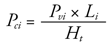
Pci is the compression force in the deck-girder from the horizontal component of the cable force,
Pvi is the vertical DL + LL force applied at the cable connection at the deck-girder plus the vertical component of the additionally-applied tension force,
Li is the horizontal distance from this connection to the tower, and
Ht is the height of this cable connection at the tower above the deck.
A simplified initial calculation for the cumulative compression force is provided by:
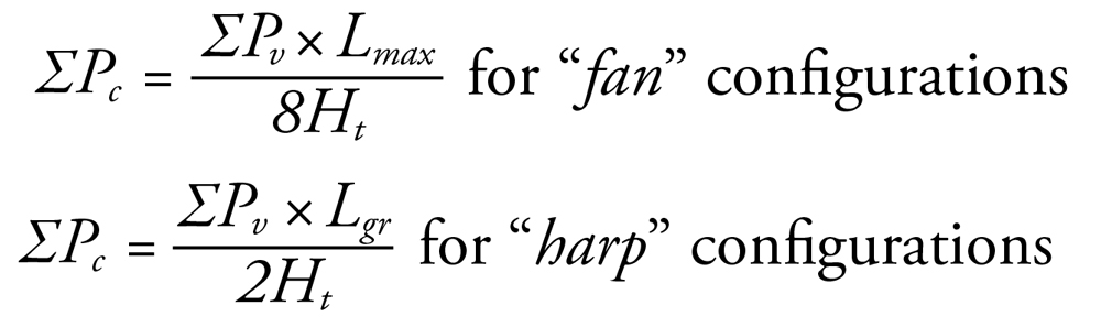 where:
ΣPc is the cumulative compression force in the deck-girder, maximum at towers,
ΣPv is the sum of all downward vertical forces on the main span deck,
Lmax is the main span length,
Ht is the height of the cable connections at the tower above deck, as shown in Figure 4 for fan or harp cable configuration, and
Lgr is the total length of the cable group for harp configuration.
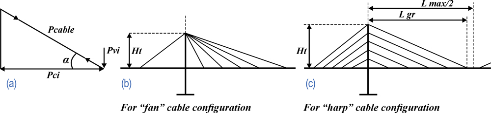
Figure 4. Compression forces in deck-girder: at single cable (a); and total compression force for “fan” (b) and “harp” (c) cable configurations.
The sum of the horizontal forces of all cables at the tower (from the main span) is equal to the cumulative compression force in the main span deck-girder, balanced by an equal force on the opposite side.
These calculations will allow the designer to establish the initial design dimensions for the cables, deck-girder, and tower to be used in the computer model for further adjustments and refinements of the system. The deck-girder has to be designed for the compression and bending from the cable-stay system and the typical bridge deck design for vertical dead and live loads. The initial approach described above will help to achieve the desired final goal faster.
Efficiency and Economy
Cable-stayed bridges are efficient in cost, materials, and construction time. They have better efficiency than other bridge systems, with the only competitor being suspension systems, while allowing for more straightforward construction methods. An additional advantage of cable-stayed bridges is their larger efficient span range from 100-meter spans (328 feet) to over 1,000-meter spans (3,280 feet).
The multitude of possibilities of the system provide engineers and architects with many design options. The “mid-long range” structures allow more creativity, originality, and possibilities for innovative work. A cable-stayed bridge does not need to be extravagant. The most straightforward bridge with a “sincere” structure is often the best and is usually elegant and attractive.
Cable-stayed bridges have a combination of elegance, slenderness, and a feeling of robustness. The national infrastructure’s demand for more bridges requires the priority of efficiency and economy.
The art of engineering requires creativity and fantasy, but engineers should avoid repetitive and illogical shapes. Creativity is essential, but “excessive originality” should only be found in justified exceptions (e.g., Christian Menn and Michel Virlogeux).
Pros and Cons
The main system advantages are:
- Fast and relatively easy construction, requiring less time to build
- Less expensive
- Multiple design options
- Large efficient span range
- Strong and resilient structures
- Attractive appearance
The main system disadvantages are:
- Still inferior to suspension bridges for super-long spans
- Requires checking deformations at all conditions
- Requires experience in both design and construction
Further Development
Like all other bridge systems, cable-stayed bridges are continuously improved based on the development of high-strength materials and new construction technologies. More valuable for engineers are the modifications of established structural systems and newer sub-systems. In addition to the increased number of cable-stayed bridges with longer spans (above 600 meters or approximately 2,000 feet), there is increasing use of the system for pedestrian bridges. The lower loads and shorter spans allow engineers to explore new approaches, transforming the building of these bridges into a testing lab for innovation. As such, we may consider the extradosed, under-spanned, and inverted Fink truss sub-bridge systems, all oriented to improved efficiency.
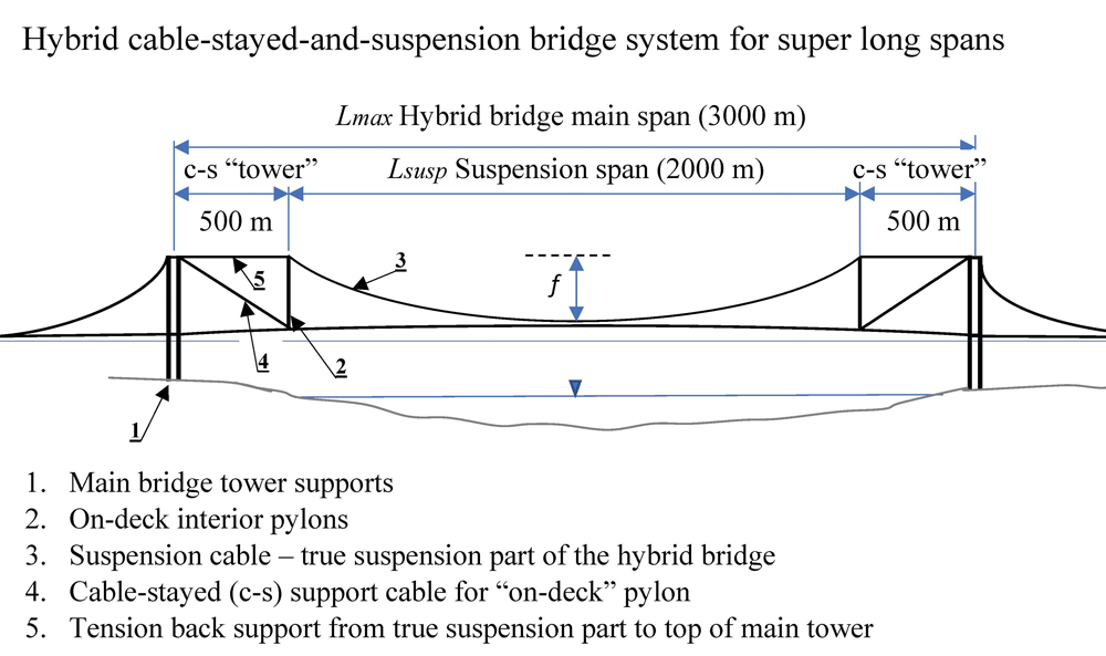
Figure 5. Hybrid cable-stayed and suspension bridge system for super long spans.
One area of further development is the pursuit of combinations/hybrids of cable-stayed and suspension bridge systems for achieving super-long spans. The idea is to reduce the suspension span length by moving the suspension support points inward along the span. This not only reduces the suspension span length but the required tower height as well while allowing a longer clear span. This is obtained with “cable-stay cantilevered alternatives” at the bridge towers, adding “on-deck” cable-stayed pylons (Figure 5). With 500-meter (1,640-foot) cantilevers and cable-stayed “on-deck” pylons used on each side of a total clear span of 3,000 meters (9,842 feet), the suspension part is reduced to 2,000 meters (6,561 feet). Such reduction would allow using main suspension cables of the size and type of those already used in bridges, like the Akashi-Kaikyo at 1991 meters (6,532 feet), for a much longer main span.
Conclusions
Based on current technical progress and fast development, cable-stayed bridges may reach spans 2,400 to 2,600 meters (7,600 to 8,500 feet) in a short while; such design will require towers about 500 to 570 meters tall (1640 feet to 1,870 feet), something achievable, considering already completed skyscraper structures. This will extend the efficiency range for cable-stayed bridges to very long spans above 2,000 meters (6,561 feet). A hybrid cable-stayed-and-suspension system would make possible even longer spans of up to 3,000 to 3,400 meters (9,842 to over 11,000 feet), incorporating a “pure” suspension bridge of “only” 2,200 to 2,400 meters (7,218 to 7,874 feet).
Based on the efficiency and advantages of cable-stayed structures, American engineers and transportation agencies should consider more cable-stayed bridges when planning new projects. Greater use of cable-stayed bridges may upgrade the infrastructure with these efficient, faster built, and elegant structures. Making cable-stayed bridges more popular may also help our bridge engineering profession regain its position of leadership in the design and construction of long-span bridges.■