
A Creative Mass Timber Office Project
The District Office is a 90,000 square foot, six-story building in Portland, Oregon. System planning and attention to constructability resulted in the use of mass timber in this successful project.
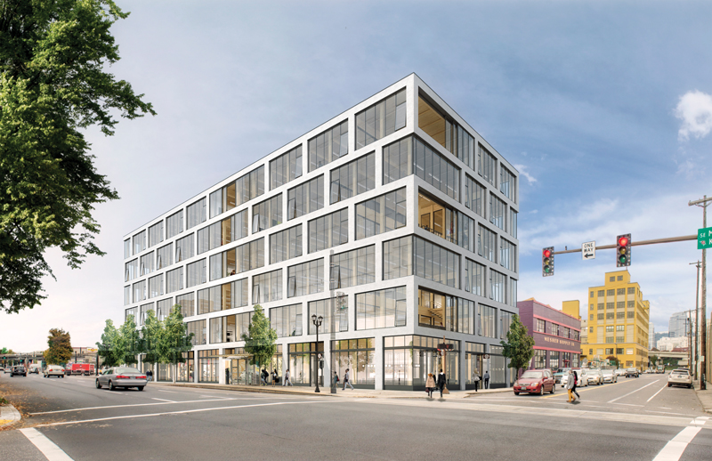
Rendering of the District Office. Courtesy of Hacker Architects.
The primary feature of the project is its exposed mass timber structure consisting of cross-laminated timber (CLT) floor panels with long-span glued laminated timber (glulam) beams supported on glulam columns at 10 feet on-center. Located on a half-block site with perimeter dimensions of approximately 100 feet by 200 feet, the rectangular plot lends to an efficient one-way span of the CLT floors.
Above grade, the mass timber gravity frame is tied to special reinforced concrete shear walls with a concrete diaphragm. At ground level, the post-tensioned concrete slab spans over the below-grade parking garage. Once completed, District Office will offer flexible retail, office, and restaurant space to the neighborhood.
Design Elements
Optimization of the structure was among early efforts to make the mass timber building a reality. Pricing studies were performed to determine optimum floor assembly; the final selected assembly consists of a 3-inch concrete topping slab over 3-ply CLT panels. The CLT panels support gravity loads while the reinforced concrete topping slab provides diaphragm capacity and contributes to a one-hour fire rating.
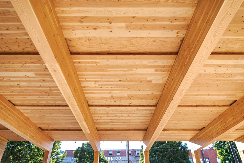
The beam spans range from 30 to 40 feet and bear over the full area of the glulam columns such that each column has a single beam framing into it. The long spans and the tight column spacing create an open floor plan with a central colonnade over the length of the building. The glulam members and the CLT floors are all Douglas Fir-Larch manufactured locally in Oregon with lumber sourced from California.
The design uses the minimum office live load criteria per ASCE 7-10, Minimum Design Loads for Buildings and Other Structures; however, vibrations become an important design consideration when long-span glulam beams and light-weight floors are combined. The floor assembly and glulam beams were analytically modeled to understand cumulative effects, and in-situ testing was performed to verify results. KPFF, in collaboration with Woodworks and others, is currently finalizing a design guide funded by a USDA Forest Service Grant for vibrations in mass timber construction that will incorporate the results from the District Office analysis.
With the tight column spacing above grade, wide, shallow post-tensioned transfer beams are used in the ground floor post-tensioned slab to allow for drive aisle clearance and optimized parking in the garage. Column locations in parking garages always require close coordination. To limit the number of transfer beams at the post-tensioned slabs, careful coordination of column locations in the parking garage below was necessary.
Architectural Consideration
One of the primary architectural objectives was to fully expose the wood structure. This required connection designs that were aesthetically thoughtful as well as structurally effective. Accommodating fire design was also necessary. The glulam beams and columns meet a one-hour fire-resistance rating in accordance with the 2012 National Design Specification® (NDS®) for Wood Construction. An effective char layer of 1.8 inches was used at all exposed wood surfaces to calculate the fire resistance.
Due to individual connection complexity, the repetition of custom connections became important for both detailing and constructability. The primary beam-to-column connection had only four variations that were used in over 350 locations. This connection consists of a single pipe extending through the beam and CLT panel to the column above, which is possible as there is only one beam framing into each column. The pipe was designed to cantilever off the top of the glulam column with any resulting moments resolved in the bearing plate that is attached with long screws into the column end grain. The cantilevered pipe column eliminates any hinge behavior, providing lateral stability as well as a load path from column-above to column-below through the pipe. As the pipe redirects the load path, the CLT panel and glulam beam are not loaded perpendicular to grain. This resulted in a simple, repeatable connection protected from fire exposure and hidden from view.
The entrance of natural light was also important to the architectural design. The floor-to-floor height at the building perimeter was maximized so the windows could extend to the ceiling. Perimeter beams were eliminated where possible, using composite action of the CLT panel and concrete floor to support the exterior wall assemblies. Where perimeter beams could not be eliminated, upturned beams were used to maintain a consistent rough opening.
Accommodating Mechanical Systems
Coordination of the mechanical systems occurred at an early phase to effectively expose the structure since the building required an organized, pre-determined path to serve each floor. Two solutions arose and drove the framing layout: a central colonnade open to all bays and continuous chases above the beams.
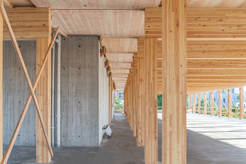
Central colonnade at concrete core.
The central colonnade provided a path for the main mechanical runs to reach the north and south ends of the building. The full ceiling height was maximized by embedding steel beams in the depth of the CLT panel. The steel was installed in the CLT panels, then covered by concrete topping above and fire-protected from below. Keeping the steel beams in-plane with the CLT panels allowed the mechanical, electrical, and plumbing (MEP) systems to be located tight to the structure. The mechanical output could successfully turn to run parallel between beams and distribute to the east and west ends of the building.
To further integrate the mechanical system, gaps between the CLT panels were provided, creating mechanical chases. Small lines, such as sprinklers, can distribute to any location in the building without penetrating beams while minimizing visual impact. The floor framing at the chases are composed of Douglas Fir-Larch plywood panels spanned by the concrete topping slab. The chase load is re-distributed to adjacent panels via the concrete topping such that the CLT panels are designed for their own load plus tributary load from adjacent chases.
Future Flexibility
One interesting design criterion was flexibility for future tenants. This was an early consideration since exposed timber construction cannot be modified as easily as a hidden structure while still maintaining the architectural intention.
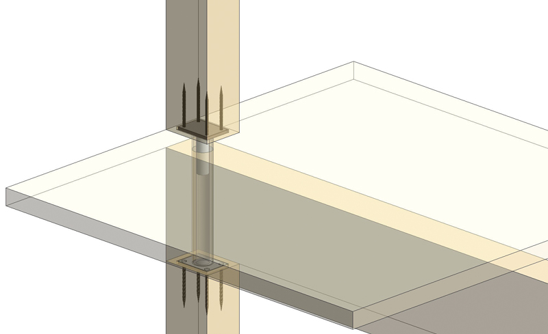
Rendering of typical beam-to-column connection.
Tenant flexibility was accommodated by incorporating designated spaces for future large floor openings. At each selected location, 7-ply CLT panels were used to span 20 feet with upsized beams and columns. The lateral analysis required evaluation of the diaphragm and shear wall behavior with these distinct portions of floor panels removed at each level.
CLT chases over glulam beams.
Lessons Learned from Construction
Creating a mock-up of the primary beam-to-column connection was critical. Seeing the build-up of this custom connection provided an understanding of how to improve its constructability, along with discussing with the rest of the design team how it transferred load. This unique construction perspective provided an understanding of the required tolerances and fit-up that is challenging to get from computer renderings alone. More importantly, the mock-up allowed the team to minimize unforeseen issues before fabrication and construction.
District Office combined concrete and timber construction, each material having very different tolerance limits. This concept was understood during design, but additional tolerance constraints were discovered during construction. For example, the contractor, Andersen Construction, was thoughtful when it came to ordering the glulam beams that framed to the concrete core. They had the glulam beams manufactured long so they could cut each beam to length based on the as-built location of the core. The CLT chases allowed for flexibility within the panel layout. When the concrete core was out-of-plumb, but within concrete tolerance, that dimension could be absorbed within the chase. For future applications, consideration may be given to tightening tolerances specified on unique concrete elements where differential tolerances accumulate and become difficult to accommodate. Detailing needs to be carefully considered where wood frames into concrete regarding both plumbness and levelness.
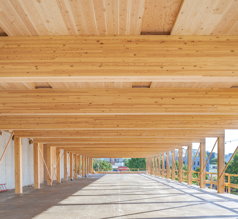
Long-span glued laminated timber beams.
One of the biggest lessons learned is to keep the wood connections simple. Just like any other construction material, limiting connection type and complexity is helpful for constructability. Reflecting on the detailing process helped with the realization that the number of screw types needs to be limited. It is great to optimize design, but it is not always best for construction.
Structural Investigations
Tenant space for the project architect, Hacker Architects, was included in the scope of the core and shell design for District Office. They desired to feature an honest mass timber staircase, remaining true to the concept of a mass timber building. KPFF teamed with Hacker and Freres Lumber to produce the concept of an all mass plywood panel (MPP) stair. The stair features intricately cut stringer shapes of mass plywood panels that are then combined to form a true wood stair.
Calculations for the stair were unable to be performed due to a lack of product data specific to the unique stringer geometry. KPFF Structural and KPFF Structural Investigation Group (SIG) developed a testing plan conforming to Chapter 17 of the 2014 Oregon Structural Specialty Code for pre-construction load testing. Required loads were applied at various time intervals, as prescribed in the testing plan, and deflection and rebound measurements were taken. Following positive results of pre-construction load testing, a testing report was written and submitted as part of the stair package. This resulted in a code-approved path for the mass plywood panel stairs satisfying Hacker’s desire for a true wood stair.
Looking Forward
The demand for mass timber continues to grow as a modern-day construction material and is increasingly being considered by developers and architects. The State of Oregon now recognizes specific building types to accommodate mass timber construction, showing positive progress toward more regular use. District Office has proven to be a success story of how thoughtful system planning, along with constructability considerations, can result in a cost-competitive, beautiful building.■
Project Team
Owner: Beam Development & Urban Development + Partners
Structural Engineer of Record: KPFF Consulting Engineers
Architect of Record: Hacker Architects
Contractor: Andersen Construction
Mass Timber Supplier: DR Johnson