
Is the Wind Blowing in the Right Direction?
The ASCE 7-16, Minimum Design Loads for Buildings and Other Structures, has been published in accordance with the International Building Code (IBC 2018), incorporating updates regarding wind load calculations from ASCE 7-10. This article relates to wind uplift on flat and gable roofs of major logistic centers with slopes ≤ 7 degrees and buildings ≤60 feet in height. The article focuses on the wind uplift loads on the roof elements of joists and girders. For joist wind uplift loads, the method of Components and Cladding in Chapter 30 of ASCE 7 is adopted. For girders, considering the effective wind area is larger than 700 square feet for typical major logistic centers, the Main Wind Force Resisting System (MWFRS) method in Chapter 27 is adopted.
The wind load updates can affect the design of roof joist and girder elements. The sizes and bracing required can be reduced if the wind uplift loads are smaller. The updates are examined by selecting multiple cities in the U.S. and comparing the results. A case study in the city of North Las Vegas is also presented to show the influence on the design of roof joists and girders.
Basic Wind Speed Comparisons
In ASCE 7-16, the basic wind speeds are updated for risk category II buildings, and many cities see a significant reduction. Figure 1 summarizes the differences for risk category II buildings in major U.S. cities. The values are derived directly from the maps, and special wind zones are not considered. For Houston, Miami, New Orleans, and New York City, the basic wind speeds remain the same. For the remaining major U.S. cities, the basic wind speeds are decreased by 1.7% to 11.8%.
Roof External Uplift Pressure Coefficients
The roof External Pressure Coefficient (GCp) comparison in this article is only limited to ASCE 7-16 Figure 30.3-2A, which is updated from ASCE 7-10 Figure 30.4-2A, for components and cladding of buildings with height less than 60 feet and gable roofs with θ ≤ 7 degrees.
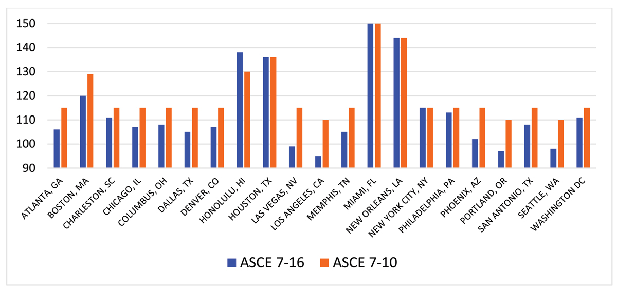
Figure 1. Basic wind speed (mph).
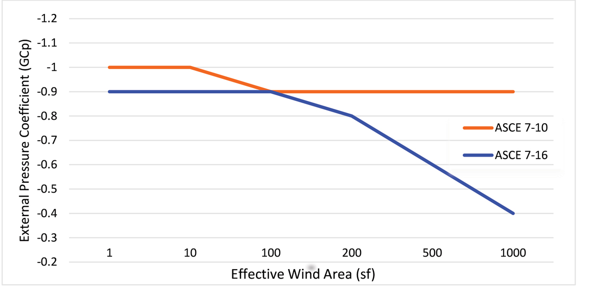
Figure 2. External pressure coefficient comparison for center zone.
The first significant change is the zone divisions. Another major change is the external pressure coefficients with respect to the effective wind areas. Figure 2 shows the comparison of external coefficient values between ASCE 7-16 and ASCE 7-10 at the center zone. In Figure 2, if the effective area is 500 square feet, the value can be reduced by 40% and, when the area becomes more, the reduction can be up to 60%.
Joist Framing Wind Uplift and Pressure Comparisons
The method used to calculate wind uplift and downward pressure for the design of joist framing is adopted from ASCE 7-16 and 7-10 Chapter 30, Wind Loads: Components and Cladding. The comparison is based on an effective wind area of 400 square feet. For ASCE 7-10, the building type selected is Building Enclosed. For ASCE 7-16, two building types are considered, Building Enclosed and Building Partially Enclosed.
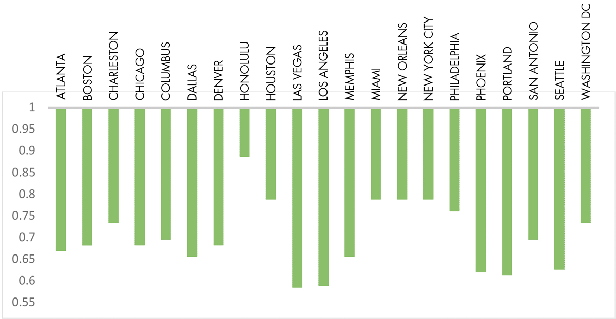
Figure 3. Roof joist wind uplift pressure ratio.
Figure 3 shows the roof joist wind uplift pressure ratio between ASCE 7-16 Enclosed Building and 7-10 Enclosed Building. Note in Figure 3 that all the cities see a significant decrease of 10% to 40% due to the reduction of external pressure coefficients.
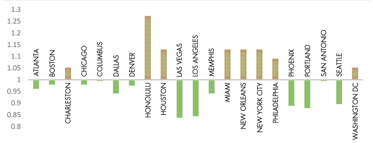
Figure 4. Roof joist wind uplift pressure ratio.
Figure 4 shows the roof joist wind uplift pressure ratio between ASCE 7-16 Partially Enclosed Building and 7-10 Enclosed Building. Due to the higher internal pressure coefficient, Charleston, Houston, Miami, New Orleans, New York City, and Philadelphia see an increase from 5% to 27%. However, Atlanta, Boston, Chicago, Columbus, Dallas, Denver, Las Vegas, Los Angeles, Memphis, Phoenix, Portland, San Antonio, and Seattle still see up to 15% reduction.
Why compare ASCE 7-16 partially enclosed to ASCE 7-10 enclosed? For many buildings, structural engineers consider “enclosed” as the default. However, “partially enclosed” can give more flexibility when considering future uses of a building. A minimal increase in the pressure ratio between enclosed and partially enclosed may provide additional options by using ASCE 7-16 partially enclosed.
Girder Framing Wind Uplift Comparisons
Per ASCE 7-16 and ASCE 7-10 30.2.3, component and cladding elements with a tributary area greater than 700 square feet shall be permitted to be designed using MWFRS provisions. Assuming the roof girders have a tributary area larger than 700 square feet, which is very common for industrial buildings, the roof uplift pressure calculation can be based on Chapter 27, Wind Loads on Buildings-MWFRS.
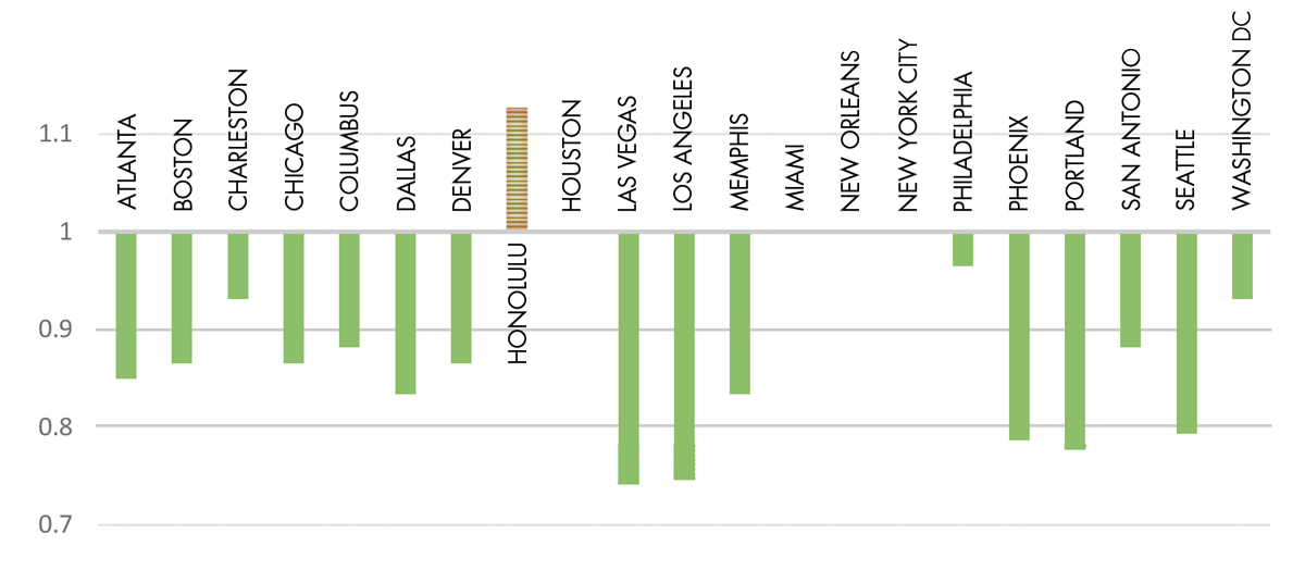
Figure 5. Roof girder wind uplift pressure ratio.
Figure 5 shows the roof girder wind uplift pressure ratio between ASCE 7-16 Enclosed Building and 7-10 Enclosed Building. From Figure 5, note that Houston, Miami, New Orleans, and New York City have the same value, whereas all the rest of the cities see a decrease of 5% to 15%.
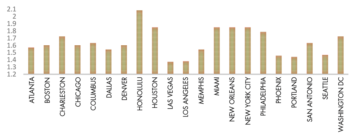
Figure 6. Roof girder wind uplift pressure ratio.
Figure 6 shows the roof girder wind uplift pressure ratio between ASCE 7-16 Partially Enclosed Building and 7-10 Enclosed Building. It can be concluded that due to the higher internal pressure coefficient, all the cities see an increase.
Case Study
A case study in the city of North Las Vegas demonstrates the comparison of wind uplift pressure for roof elements, including joists and joist girders. The results shown are wind-net-uplift pressures using a load combination equal to 0.6D-0.6W. The dead load is taken as 8.5 psf for a joist and 10.5 psf for a joist girder considering roofing, plywood, rafters, sprinklers, and member self-weight. No miscellaneous loads are considered.
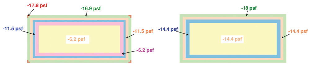
Figure 7. Joist net uplift – ASCE 7-16 enclosed building. Joist net uplift – ASCE 7-10 enclosed building.
Figures 7, 8, 9, and 10, show four different comparisons of roof element wind net uplift. They are joists under ASCE 7-16 Enclosed Building vs. 7-10 Enclosed Building, joists under ASCE 7-16 Partially Enclosed Building vs. 7-10 Enclosed Building, joist girders under ASCE 7-16 Enclosed Building vs. 7-10 Enclosed Building, and joist girders under ASCE 7-16 Partially Enclosed Building vs. 7-10 Enclosed Building. The values of the case study reflect the analysis presented above.

Figure 8. Joist net uplift – ASCE 7-16 partially enclosed building. Joist net uplift – ASCE 7-10 enclosed building.
For the center zone, the joists see a reduction for both comparisons. There is a significant reduction for girder joists when comparing ASCE 7-16 Enclosed Building and 7-10 Enclosed Building and slight increase between ASCE 7-16 Partially Enclosed Building and 7-10 Enclosed Building.
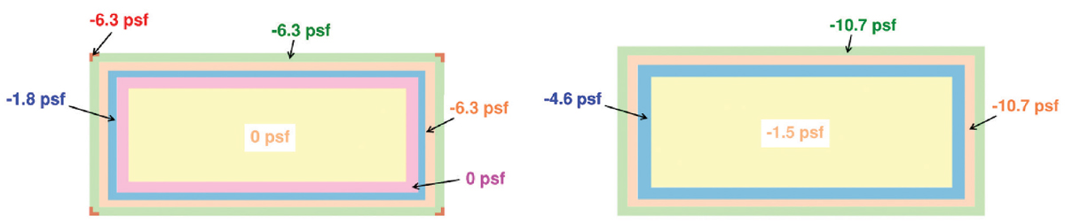
Figure 9. Joist girder net uplift – ASCE 7-16 enclosed building. Joist girder net uplift – ASCE 7-10 enclosed building.
The reduction of net wind uplift on roofs could reduce the joist and joist girder cost by cutting down the bottom chord size and joist brace spacing. For the case study project in the city of North Las Vegas, comparing ASCE 7-16 Enclosed Building type with 7-10 Enclosed Building type, the roof joist net-uplift in the major center area is reduced from -14.4 psf to -6.2 psf. The bottom chord of the joists will see significantly less compression forces. The joist bottom chord size can be reduced from LL 2 x 0.203 to LL 2 x 0.145, and joist brace spacing can be relaxed to 12 feet from 10 feet. The reduction in the brace quantity will reduce the cost for the braces from the manufacturer and the install cost due to fewer braces.
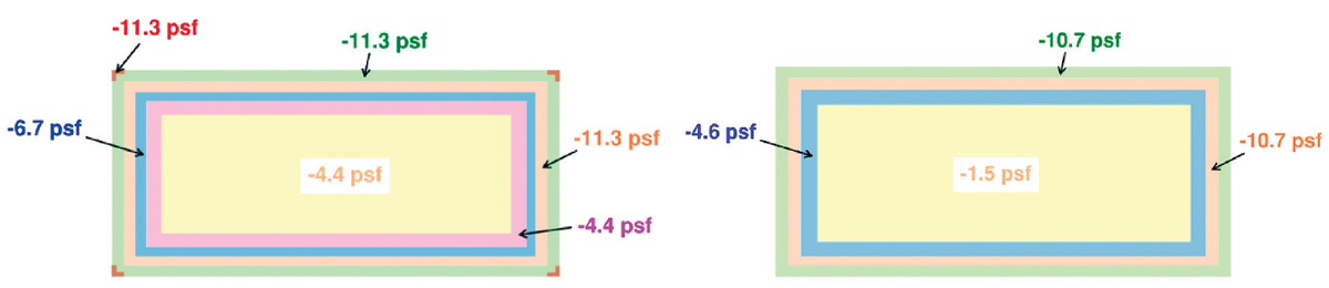
Figure 10. Joist girder net uplift – ASCE 7-16 partially enclosed building. Joist girder net uplift ASCE 7-10 enclosed building.
The steel takeoff and cost reduction will depend on project location, the nature of the project, and contractors. The numbers above are the estimated impacts for the case study project, applicable in this article only.
Conclusion
As noted earlier, ASCE 7-16 basic wind speeds are updated for risk category II buildings. Wind speeds have remained the same or have been lowered for the major U.S. cities studied in this article.
It is also noted that, within the center area of the roof, the external uplift pressure coefficients from ASCE 7-16 are reduced significantly, by up to 60%, for the major center zone, as shown in Figure 2. The reduction of the external uplift pressure coefficient, combined with a reduction in basic wind speed, yields a significant reduction in roof wind uplift for many U.S. major cities. Results of the roof net uplift case study in the city of North Las Vegas illustrate the potential for significant savings from wind load reductions for both joists and joist girders and, as a result, lower overall construction material cost.■