
As buildings get taller, bigger, and are required to resist higher seismic forces, the amount of reinforcement needed becomes impractical. Even if theoretical sizes can be calculated, it may be impossible to construct tightly spaced rebar cages or congested joint connections. Using higher strength reinforcement is a natural solution to this problem. Research on the use of high-strength reinforcement (HSR) began in the late 1950s. The outcome of this research first appeared in ACI 318-71, Building Code Requirements for Structural Concrete, which allowed limited use of reinforcement with a higher grade than 60 ksi. However, the maximum yield strength of reinforcement in elements resisting seismic loads was limited to 60 ksi. This restriction remained in the building code until recently due to a lack of data on cyclically loaded members with HSR. The main expected advantage of HSR over conventional reinforcement (CR) is a lower volume of reinforcement material in construction, resulting in lower construction time and costs (Price et al. 2013). In 2014, two reports identified experimental tests required and provisions of ACI 318 that would need to be updated to allow the use of HSR in seismic applications (ATC 2014; NIST 2014). Later, extensive research answered many of the identified gaps (the online version of this article includes a summary of this research). This article introduces changes in ACI 318-19 related to the use of HSR and presents considerations engineers should be cautious of before specifying HSR.
Changes Related to HSR in ACI 318-19
In response to the research, ACI 318-19 introduces significant changes allowing more applications of HSR in concrete buildings. ACI 318-19 was released in July 2019 and will likely be referenced in the 2021 IBC. Reinforcement in special lateral force resisting systems, which were previously limited to Grade 60 for flexural, axial, and shear reinforcement, can now use up to Grade 80 or Grade 100 depending on the application. Additionally, various gravity elements, which were previously limited to Grade 80, are now extended to Grade 100. Refer to Table 1 for a summary of major reinforcement grade changes from ACI 318-14 to ACI 318-19.
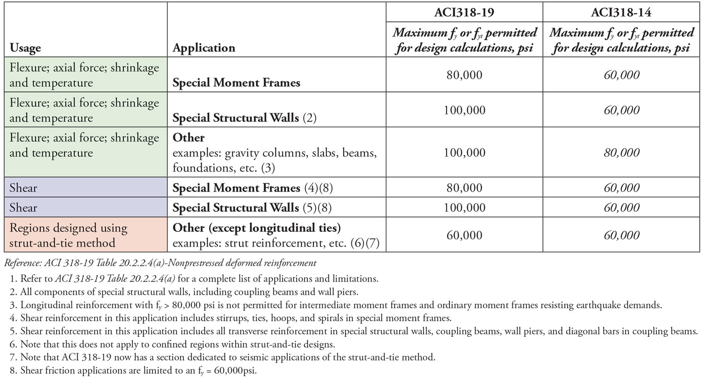
Table 1. Changes in use of reinforcement grades between ACI 318-19 and ACI 318-14.
Reinforcement Specification Requirements
These revisions occurred without the introduction of new ASTM specifications for HSR. Despite this, the adoption of higher grades was not independent of new refinements to rebar manufacturing. The ACI 318 Committee chose to address these refinements directly in the code, in Chapter 20, by setting requirements for smoother bar deformation profiles, various minimum strength ratios, and minimum elongations before fracture. For ASTM A706, the requirement on deformation profiles calls for “the radius at the base of each deformation… be at least 1.5 times the height of the deformation.” This requirement is intended to avoid low-cycle fatigue cracks at these locations along the bar and improve the number of half-cycles to fracture. These new provisions apply to ASTM A706 Grade 60 reinforcing as well.
Detailing Enhancements
Perhaps the most significant changes to designing with HSR relate to detailing requirements. In past versions of the code, engineers could use two equations to calculate development and lap lengths. Those two equations remain largely the same except for an added reinforcement grade multiplier (ψg) that is equal to 1.0 for Grade 60, 1.15 for Grade 80, and 1.3 for Grade 100; Example 1 illustrates splice length calculation according to ACI 318-19 with f´c = 6 ksi. Also note that, for lap splices of HSR, the code now requires a minimum amount of splice confinement provided by transverse reinforcement along the splice.
Example 1. Splice Length Calculation
Ls (#11, Grade 60, 6 ksi) = 6’-0”*; best case** = 3’-7”
Ls (#11, Grade 80, 6 ksi) = 6’-0” x (80 ksi/60 ksi) x (1.15)
= 9’-3”*; best case** = 6’-6”
Ls (#11, Grade 100, 6 ksi) = 6’-0” x (100 ksi/60 ksi) x (1.3)
= 13’-0”*; best case** = 7’-9”
*Use of equation in Table 25.4.2.3 (traditionally used by structural engineers for most typical conditions without epoxy coating)
**Best case refers to the upper limit where (cb + Ktr)/db = 2.5, in conjunction with Eq. 25.4.2.4a
The minimum amount of longitudinal reinforcement for flexural members is inversely proportional to reinforcement yield strength and hence is lower for HSR than for CR. However, 80 ksi is the maximum yield strength permitted to be used in equations in 9.6.1.2, equating minimum reinforcement areas for Grade 80 and Grade 100. For special structural walls, the minimum reinforcement area follows the same pattern, except the steel yield strength is not limited in this calculation (18.10.2.4). The maximum longitudinal reinforcement ratio in special moment frame beams is lowered to 0.02 for Grade 80 reinforcement (18.6.3.1).
Tighter transverse tie spacing is required for seismic systems using HSR to inhibit longitudinal bar buckling under higher axial stresses. The maximum spacing in the plastic hinge region is decreased to 5db for Grade 80 in special moment frames (18.6.4.4 and 18.7.5.3), and to 5db and 4db for Grade 80 and Grade 100, respectively, for special shear walls boundary elements (Table 18.10.6.5(b)).
Additionally, stricter limitations exist for the use of mechanical splices of HSR in seismic applications and should be considered early in the design process (18.2.7.2). Headed bar provisions (25.4.4.1) have seen multiple changes, one of which directly applies to HSR. The previous limitation of fy to 60 ksi for the use of standard class HA headed bars has now been removed, opening its application to HSR.
Stiffness Considerations
HSR allows for proportionally less area of steel to resist the same strength demands as traditional reinforcement. This economy can result in a decrease in member stiffness, which should be considered. Most notably, this decrease is evident in minimum 2-way slab thickness limitations for which deflections need not be calculated; the minimum thickness limitation for 2-way slabs using Grade 80 reinforcement is approximately 10% and 20% larger than when using Grade 60 and Grade 40, respectively (Table 8.3.1.1).
For lateral analysis, this consideration is not explicitly addressed by decreased modifiers for effective section stiffness in first-order linear analyses (Table 6.6.3.1.1(a)). However, some decreased stiffness has been shown in research studies. Engineers concerned with capturing this reduction more precisely could do so by using the alternative moment of inertia equations from Table 6.6.3.1.1(b).
Important Considerations
While there are many benefits to using HSR, there are times when the engineer should be cautious about specifying it. Below is a partial list of considerations that the authors believe engineers may face during design.
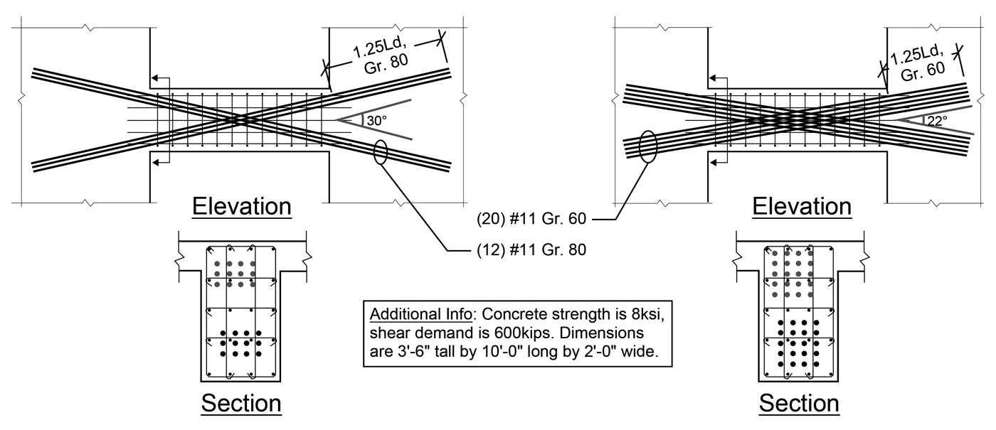
Figure 1. Comparison of similar diagonal coupling beams with the same shear capacity.
- Engineers should continue to use fy of 60 ksi in their calculations for shear friction. Shear friction may begin to govern designs as the total area of longitudinal reinforcement is reduced with HSR. Correspondingly, greater attention should be paid to roughening construction practices if shear friction becomes critical in the design.
- Larger crack widths correspond to HSR yielding. This may adversely affect certain serviceability criteria, such as steel corrosion.
- From experience with HSR, it is the authors’ opinion that all HSR should be very clearly marked to distinguish it from typical reinforcement on a job site; a common solution is the use of spray paint.
- Diagonal coupling beams, challenging to construct and typically heavily congested, could reduce diagonal reinforcement congestion through the use of HSR up to Grade 100. A secondary benefit is the production of a more favorable tie angle in the member, which will more efficiently use the diagonal reinforcement; this benefit is most pronounced with shallow diagonal coupling beams (Figure 1). In this example, the beam on the left achieves a more efficient tie angle to resist shear than the beam on the right, resulting in a reduction of bars to just 12 total in the Gr. 80 design. This is more substantial than reducing the Gr. 60 design by the ratio of stresses, 60ksi/80ksi, which would have produced 15 total bars.
- Mechanical couplers are not permitted in plastic hinge zones utilizing HSR; the code commentary permits the EOR to override this if provided with adequate product data.
- Caution should be exercised where the use of HSR indirectly reduces redundancy of reinforcement. An example would be chord or collector reinforcement taken from 2 bars (total) down to 1 bar, thereby reducing the redundancy of that element if there was a bar defect or splice failure.
- Compression members utilizing HSR can attract and sustain higher demands. As a result, buckling becomes a critical consideration. Although columns typically come to mind in this application, ends of slender shear walls can also be of concern, especially those of asymmetric T- or L-type configurations.
- In general, anchorage and force transfer should be of more concern now that higher bar stresses are being transferred. Anchorage or bond failures are more brittle and could preclude an intended ductile mechanism. An example of this would be inadequate tie development within nodal zones of strut and tie models.
- The engineer should check with suppliers on the availability of HSR. Manufacturers may have size limitations on various bar configurations.
Conclusion
For many years, using HSR in seismic applications has been restricted due to a lack of test data. However, a push from the structural engineering community has led to recent studies which alleviate the restriction on HSR in ACI 318-19. This article summarizes the research, changes in ACI 318, and various considerations that come with using HSR, mostly in seismic design applications. Changes in the ACI 318-19 include, among others, larger lap splice lengths for HSR, lower minimum longitudinal reinforcement limits, tighter transverse reinforcement spacing, and reduced stiffness of elements with HSR. The authors of this article would like to acknowledge and thank Noah Macias for editing this article.■
Research
Research on material specifications for HSR suggested a T/Y (tensile-to-yield strength) minimum limit of approximately 1.2, and minimum uniform elongation (coinciding to tensile strength) exceeding 6% (WJE 2015). These limits were imposed to promote desirable element behavior during seismic events. Slavin and Ghannoum (2015) investigated the low-cycle fatigue performance of A706 and A615 HSR through a series of bare bar tests. In these tests, pairs of HSR and conventional reinforcement (CR) bars were tested under identical conditions for direct comparison. The tests showed that HSR performed worse due to fatigue, with an average number of half-cycles to failure for HSR being 91% of that for CR. Sokoli et al. (2019) performed a comprehensive bare bar study of HSR and observed almost no buckling when the clear length of HSR was 4db or less, and that HSR manufactured by quenching and tempering withstand, in general, a more significant number of half-cycles to fracture than other manufacturing processes. Both of these studies observed a large variation in results between manufacturers and manufacturing processes.
In light of different low-cycle fatigue performance of HSR and CR, Zhong and Deierlein (2019) performed an analytical study of the behavior of 4- and 20-story special moment frames and 8- and 42-story shear wall systems with CR and HSR under seismic loading. The study showed that the stiffness of buildings with HSR decreased, resulting in larger drifts (increases of about 20% for moment frames and 10% for shear walls). Further, the study concluded that limiting the tie spacing to 5db for HSR offsets their lower T/Y (usually 1.2 for HSR vs. 1.3 for CR) and produces similar probabilities of bar fracture and risk of collapse under MCER motions with respect to CR.
Large-scale testing included column testing, beam testing, T-wall testing, and an ongoing investigation on foundation mats. Sokoli et. al (2016) tested columns with CR and HSR under lateral loading. The columns with HSR performed adequately for seismic use, with bar fracture occurring at a drift ratio of 5.5%. To and Moehle (2017) performed tests of beams with CR and HSR with different T/Y for HSR (1.18, 1.30, and A1035 without specific T/Y) and found that the rotational capacity of beams with HSR is comparable to those with CR. However, the HSR experienced higher strain localization and bar slip. Their follow-up computational study on a 20-story moment frame found that the current procedure (ACI 318-14) produces, in some cases, unconservative results for column shear forces, and proposed an alternative procedure. Four T-shaped shear walls were tested by Huq et al. (2018), using CR and HSR with varying T/Y. The tests showed that walls with T/Y > 1.2 and uniform elongation > 6% developed similar drift capacity as walls with CR.
References
ATC 115, (2014). Roadmap for the Use of High-Strength Reinforcement in Reinforced Concrete Design, ATC-115 Report, Applied Technology Council, Redwood City, California, 197 pp.
Huq, M.S., Weber-Kamin, A.S., Ameen, S., Lequesne, R.D., Lepage, A. (2018). High-Strength Steel Bars in Earthquake-Resistant T-Shaped Concrete Walls, SM Report No. 128, The University of Kansas Center for Research, Inc., Lawrence, KS, 129pp.
NIST (2014). Use of High-Strength Reinforcement in Earthquake-Resistant Concrete Structures, GCR 14-917-30, Applied Technology Council, Redwood City, California, 231 pp.
Price, P.R., Fields, D., Lowes, L.N. (2013). The Impact of High-Strength Reinforcing Steel on Current Design Practice, Research Grant Agreement #01-13, Charles Pankow Foundation, Vancouver, WA, 219pp.
Slavin, C.M., Ghannoum, W.M. (2015). Defining Structurally Acceptable Properties of High- Strength Steel Bars through Material and Column Testing, Part I: Material Testing Report, Research Grant Agreement #05-14, Charles Pankow Foundation, Vancouver, WA, 135pp.
Sokoli, D., Limantono, A., Ghannoum, W.M. (2016). Defining Structurally Acceptable Properties of High-Strength Steel Bars through Material and Column Testing–Part II: Column Testing Report, Research Grant Agreement #05-14, Charles Pankow Foundation, Vancouver, WA, 214 pp.
Sokoli, D., Hogsett, G., Limantono, A.A., Suselo, A., Al-Tarafany, d., Rodgers, S., Ghannoum, W.M. (2019). Acceptable Elongations and Low-Cycle Fatigue Performance for High-Strength Reinforcing Bars, Research Grant Agreement #03-16, Charles Pankow Foundation, Vancouver, WA, 213pp.
To, D.V., Moehle, J.P. (2017). Seismic Performance Characterization of Beams with High-Strength Reinforcement, Research Grant Agreement #04-14, Charles Pankow Foundation, Vancouver, WA, 140 pp.
WJE (2015). Proposed Specification for Deformed Steel Bars with Controlled Ductile Properties for Concrete Reinforcement, Research Grant Agreement #03-14, Charles Pankow Foundation, Vancouver, WA, 47pp.
Zhong, K., Deierlein G.G. (2019). Low-Cycle Fatigue Effects on the Seismic Performance of Concrete Frame and Wall Systems with High Strength Reinforcing Steel, Research Grant Agreement #02-16, Charles Pankow Foundation, Vancouver, WA, 175pp.