
The International Building Code (IBC) and design standards used by structural engineers are developed with the intent to provide minimum requirements for the design and construction of a structure to help assure the public health, safety, and welfare. While a particular structural design is required to satisfy the IBC, as well as material design standards and public safety requirements, the IBC does not directly address the effects of the vertical movement of the building structure on the building enclosure. For example, what are the deflection limits for spandrel beams or slab edges that support the building enclosure?
The IBC provides deflection limitations based only on the span of the structural member; however, more restrictive limitations may govern based on properties of the building enclosure system or architectural vertical movement joint details. Enclosure systems and framing systems exhibit unique behaviors, and interaction and structural behavior between them may not be adequately accommodated using customary span-to-deflection ratios. The structural engineer will need to understand how the enclosure is expected to behave during construction and throughout the service life of the building to design a structural frame that properly accommodates the movement limitations of the building enclosure. This article is focused only on issues associated with vertical deflections. Lateral movement limitations, such as the case of whole building drift limitations, are more clearly defined in the IBC and ASCE/SEI 7, Minimum Design Loads for Buildings and Other Structures, and are not subject to creep, varying superimposed loads, or long-term deflection effects.
IBC and Material Standards
There are two types of deflection limits: the traditional limit prescribed in codes and standards based on the span of the structural member and absolute dimensional limits based on the movement capabilities of joints designed to accommodate the deflections. Deflections based on ratios of span length consider the maximum rate of change between two points along a deflected shape and are useful for preventing damage of the nonstructural material or system that is being supported by the structural member or even the member itself. With the advancement of construction materials and the increase of member spans, the traditional span ratio limit may be inadequate in some cases to prevent damage of nonstructural systems that are supported or attached to the structure.
Structural engineers should consider several interacting effects when designing structural members that support building enclosures to provide structural systems with deflection characteristics that are compatible with the enclosure system. However, deflection requirements provided in the IBC do not address this situation. The summary below describes how the IBC and design standards approach structural deflections, and how building enclosure considerations are addressed.
IBC
The serviceability requirements in the 2018 IBC limit the deflection of structural members to the more restrictive case of either the referenced material-specific standard or those deflection limit values provided in Table 1604.3. The deflection limits in this table are based on the member span length and are meant to address serviceability and limit damage to architectural finishes. Advancements in framing systems and materials have led to longer spans and greater deflections. While some modern architectural finishes have been able to accommodate these larger deflections, many building enclosure systems may not be able to accommodate the larger deflections.
ASCE/SEI 7
The Commentary Section CC.2.1 for Appendix C in ASCE/SEI 7-16 states that, in certain conditions with long spans, it may be appropriate to limit maximum deflections to prevent damage of nonstructural elements, along with the suggestion to limit deflection to 3⁄8 inch for the case of non-load-bearing partitions.
ACI-318
Deflection requirements for concrete are governed by ACI-318, Building Code Requirements for Structural Concrete and Commentary, Chapter 24, which specifies a serviceability deflection limit for concrete members of L/480 in Table 24.2.2. A footnote to the table allows greater deflection if the deflection does not damage supported or attached elements.
AISC-360
For steel structures, AISC-360, Specification for Structural Steel Buildings, does not explicitly state serviceability deflection limits for steel members supporting building enclosures but instead references AISC Steel Design Guide 3, Serviceability Design Considerations, and Design Guide 22, Façade Attachments to Steel-Framed Buildings. These guides contain useful information and guidance for developing spandrel member design criteria.
TMS 402
Section 5.2.1.4.1 of the 2016 Edition of TMS-402, Building Code Requirements and Specification for Masonry Structures, prescribes a design deflection limit of L/600 for serviceability. Earlier editions of TMS-402, such as the 2005 Edition, included an additional overall deflection limit of 0.3 inches. The 0.3-inch deflection limit has since been removed, starting with the 2008 Edition; many structural designs still apply this criterion on most applications.
Consideration should be given to limiting differential spandrel deflection to 3⁄8 inch based on ASCE commentary and historic masonry requirements for infill wall systems, and 1⁄2 inch for unitized curtain wall systems designed to accommodate vertical movements between floors within a manufactured stack joint assembly. Increased vertical movements are possible and require additional effort and coordination among project team members to accommodate proper support and movements of the building enclosure.
Building Enclosure Systems
When designing the structure for the building enclosure, understanding and accommodating for the structural behaviors of the enclosure system and materials to be used is critical. The enclosure system must support itself and allow for predictable movements of the structural building frame.
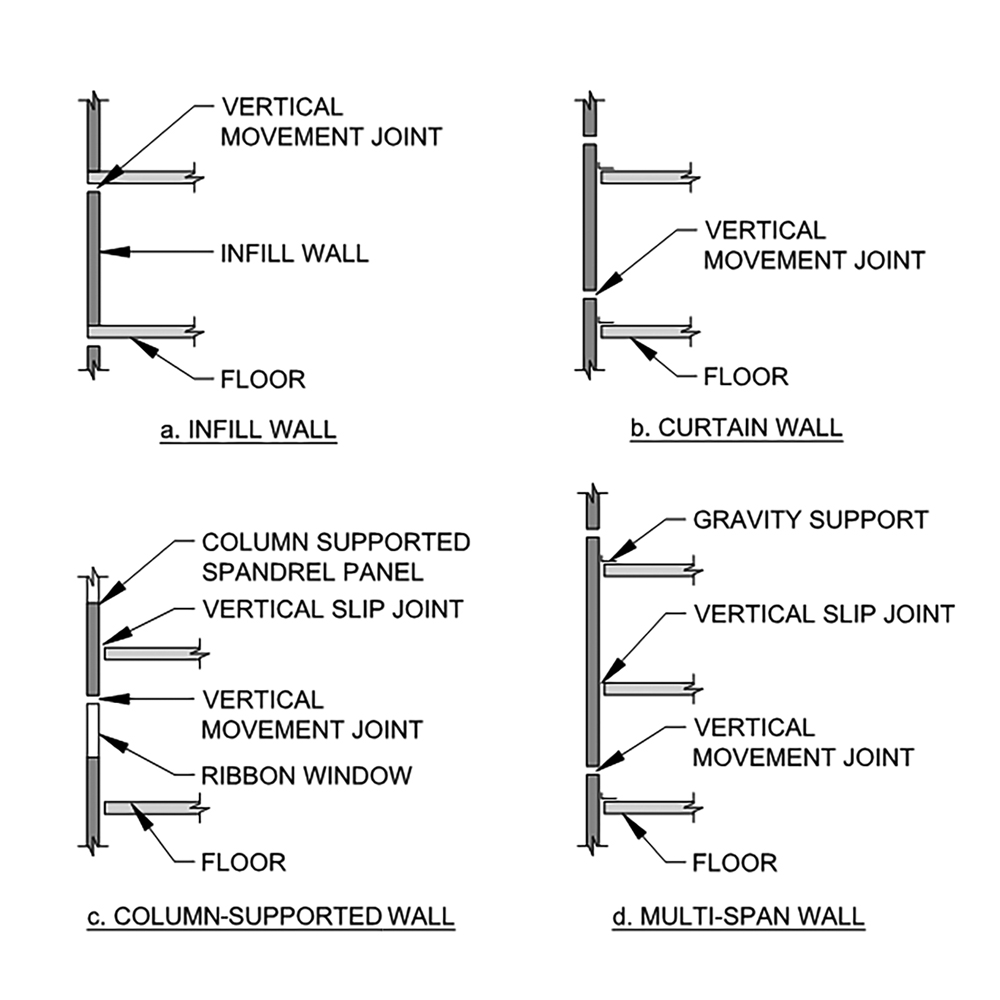
Figure 1. Common building enclosure types; a) Infill wall; b) Curtain wall; c) Column-supported wall; and d) Multi-span wall.
Infill Walls
The many varieties of infill walls, such as translucent window walls and solid-framed walls, are commonly supported by each floor level, extending and attaching to the floor above (Figure 1a). Masonry veneers, for example, are often laterally supported by an infill wall system and gravity supported at each level with a shelf angle.
Variations of floor elevation are adjusted using shims at the base of the infill wall, allowing conformance with defined vertical installation tolerances. A vertical movement joint at the top of the wall system below the floor. or below the shelf angle in the case of masonry veneer, accommodates the differential vertical displacement between adjacent floors.
Curtain Walls
Curtain wall systems are typically thin-framed wall constructions often including infills of glass, metal panels, or thin stone. The most recognizable framing for curtain walls is aluminum. The curtain wall framing is installed outboard of the structure, extending past the outer face of the structural framing. As shown in Figure 1b, the curtain wall framing is directly attached to the main building structure and does not carry the floor or roof loads of the building. Lateral and gravity loading imposed on the curtain wall are transferred to the structural building frame. Curtain walls are typically laterally supported at each level. Gravity supports can be located at each floor level or designed to span multiple levels (Figure 1d).
It is essential to understand the interaction of the wall system support locations and vertical movement joint details and capabilities, considering the various combinations of loads that may be present in-service. This is particularly true when curtain walls accommodate the accumulated movement of multiple structural levels.
Column-Supported Walls
In some cases, enclosure panels are designed to be supported from columns. A common type is a precast spandrel panel installed in front of the floor slab, typically supporting an infill ribbon window system (Figure 1c). Though the floor does not support the enclosure, floor deflection relative to the column-supported panel should be considered.
Cantilevered Perimeter Framing
Traditional deflection limits based on individual member spans do not adequately address cantilevered perimeter framing. The traditional deflection limits apply only to relative member deflections, which are measured as the difference between member ends and deflection along its span (Figure 2). While individual members of a cantilevered system can meet IBC deflection limitations, when relative deflections are combined, the resultant deflection can be significant and must be accommodated by the building enclosure system (Figure 2).
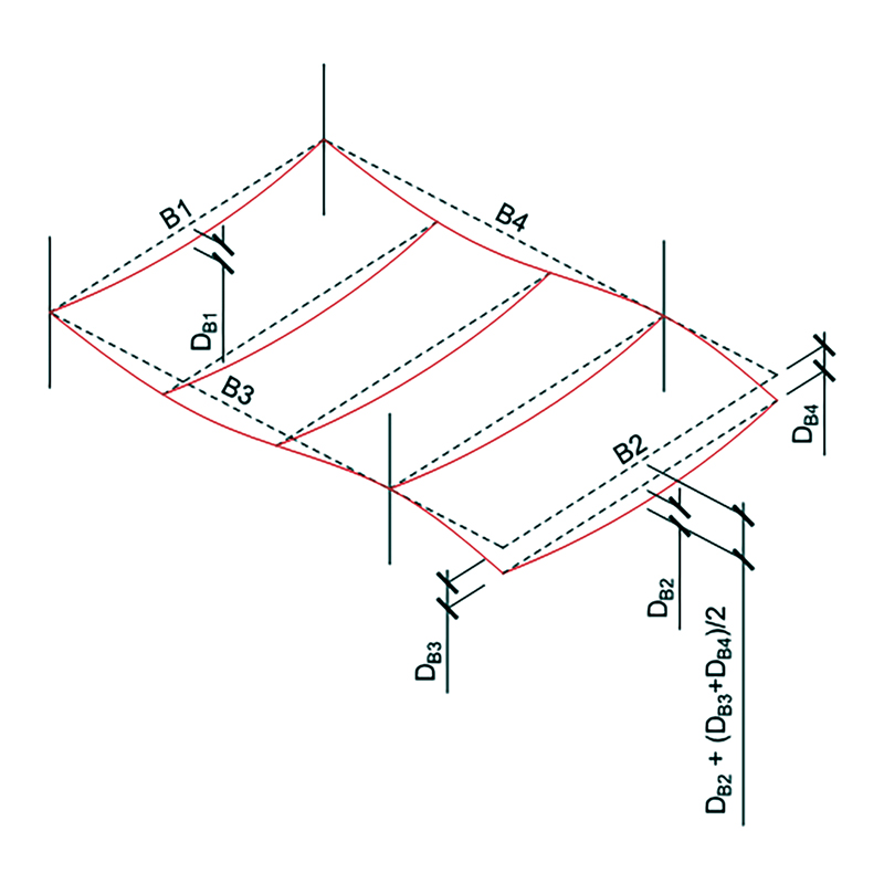
Figure 2. Relative spandrel member deflections (DB1 and DB2) are similar, but the global deflection along B2 is additive to the cantilevered end deflections.
Sizing Vertical Movement Joints
The detailing of horizontal sealant and curtain wall joints to accommodate vertical movement is not typically in the structural engineer’s scope of services. However, the structural engineer must be knowledgeable of the structural behavior of the project’s building enclosure and assist the design team by providing sizing criteria for items such as joints and defining movement requirements, including limitations for the building enclosure.
Variables that affect vertical movement within the horizontal joints are broken into two categories – enclosure movement and structural frame deflections.
Dimensional Changes of Enclosure Materials
Volumetric changes of materials need to be considered when determining appropriate widths for enclosure vertical movement joints. Temperature affects all materials differently. The rate of thermal expansion for aluminum is approximately twice the rate for concrete or steel and four times that of clay masonry. Since the curtain wall and infill window wall systems are typically built with aluminum extrusions and can experience extreme changes in temperature, the calculation of the thermal volumetric change is fundamental to determining appropriate joint widths. While manufacturers of fabricated enclosure systems, such as curtain walls, will determine the expected volumetric changes within their system, the architect will be responsible for determining the volumetric change of most infill wall systems, such as concrete and clay masonry veneers which will experience some permanent contraction or expansion, respectively, over time.
Structural Frame Deflections
When sizing enclosure vertical movement joints at locations where floor stiffness and loadings are similar between adjacent levels, the differential deflection between the levels can be estimated using a portion of the calculated deflections. However, where stiffness and loading vary (e.g., a 1st-floor wall with a stable and stiff foundation), the joint between the elevated framing and the foundation will need to account for all of the elevated frame deflection.
Even when the structural floor framing is repetitive, changes in curtain wall weight, floor finishes, and construction methods could result in differential deflection between levels. The enclosure system weight can vary due to changes in materials or height of wall sections, such as where lower or upper-level sections of a hung curtain wall may differ from the typical floor-to-floor section. Floor finishes or dead load may also vary between floors. In the case of an office tower, the flooring may not be selected or installed until a tenant has signed a lease. In this case, some floors may have installed flooring while the adjacent floor may remain unfinished for years. Though the structural design may account for heavy thickset tile flooring, a tenant may opt for a lightweight floor, such as wood or carpet. Lastly, even though the design stiffness may be identical between floors, as-built irregularities may cause the two floors to deflect differently.
Live Load Deflections
Reduction of live loads when determining spandrel deflections is appropriate. Reductions can be based on code-calculated values or a more realistic percentage depending on the application. ASCE/SEI 7-16 Appendix C Commentary suggests using 50% live load when combined with long-term effects. In addition to a uniform reduction of live loads for deflection calculations, one should also consider pattern loads where the floor plate is cantilevered. In this specific case, a loaded back span could result in upward movement at the cantilever edge, whereas loading just the cantilever portion may result in more significant deflections when compared to uniform loadings (Figure 3).
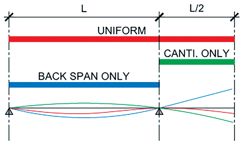
Figure 3. Deflected member shape based on uniform and pattern loading of a cantilevered member.
Long-Term Deflections
In addition to initial elastic deflection, concrete also exhibits additive long-term deflections due to creep and shrinkage. Long-term flexural deflection of horizontal members and axial shortening of columns due to both initial and long-term effects all need to be carefully considered when dealing with taller buildings, as the building enclosure installation will likely begin before the structure is complete and before initial and long-term deflections have taken place.
Coordination
There must be communication and design coordination between all members of the project design team, including the building structural engineer, architect, and various design professionals. There should be a clear understanding of how the structure will interact with the building enclosure, including the proposed support locations, loads, and deflection limitations. The design parameters should be conveyed in the contract documents and then checked throughout the submittal process. Whatever deflection limitation or assumption is used during the design of the structural frame, it should be included in the building enclosure specification or defined preferably on the architectural drawings. Well-coordinated building enclosure and structural support systems will significantly reduce possible constructability and performance issues related to the interaction of the building structure and wall enclosure systems.
Final Thought
The IBC and industry standards do not provide prescriptive requirements with respect to resultant deflection limits of perimeter floor framing members, which are attached to or support building enclosures. As such, the design team must consider the behavioral differences and provide an appropriate analysis that addresses the impact of wall enclosure systems on each project.■