
Complex Structural Systems for the Jewel Changi Airport
Jewel Changi Airport, a nature-themed entertainment and retail complex on the landside at Changi Airport, Singapore, is their newest development, opening this year. The unusual building, conceived by the firm Safdie Architects, extends the airport’s principal function as a transit hub to enfold an interactive civic plaza and marketplace, combining landside airport operations with expansive indoor gardens and waterfall, leisure facilities, retail, restaurants, a hotel, and other spaces for community activities. The combined intensive marketplace and paradise garden create a new civic center – “the heart and soul” of Changi Airport, as the airport leaders call it – and a new paradigm for community-centered airport design.
A toroidal form was chosen by the design team for the 1.4 million-square-foot glass-enclosed building. BuroHappold and Safdie Architects conceived a “gridshell” concept for Jewel’s roof and façade system that sits at the edge of level five of the ring-shaped steel and concrete base building. This perimeter support defined a span of more than 650 feet (200 meters) at its widest point. With only intermittent supports in the garden, this resulted in a nearly column-free interior. The geometry of the roof also accommodated an indoor rain-fed waterfall at its center, activated by pumped water during dry weather.
The Initial Idea
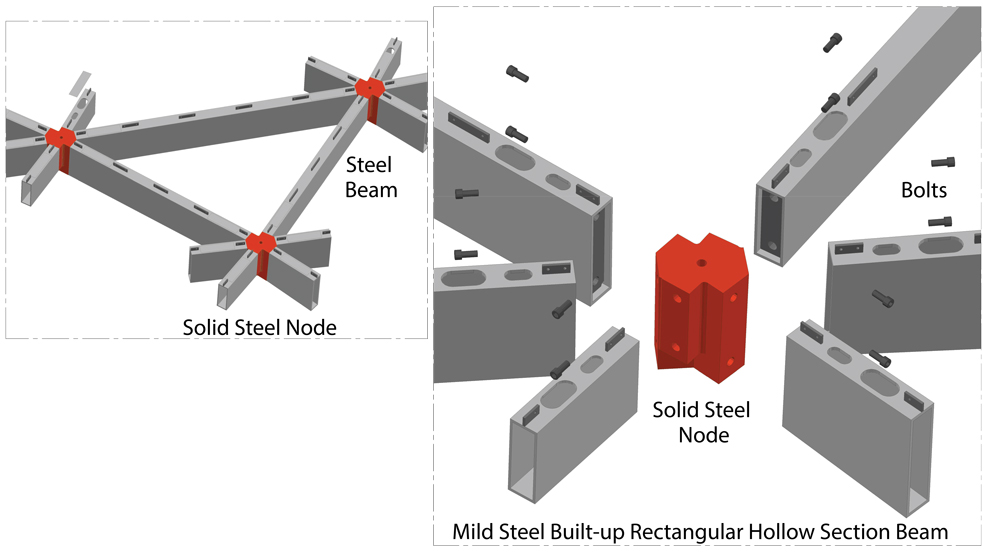
The initial “gridshell” concept was a single layer structural system that would maximize light and transparency within the space. This steel and glass shell is made of prismatic steel elements intersecting at solid steel nodes.
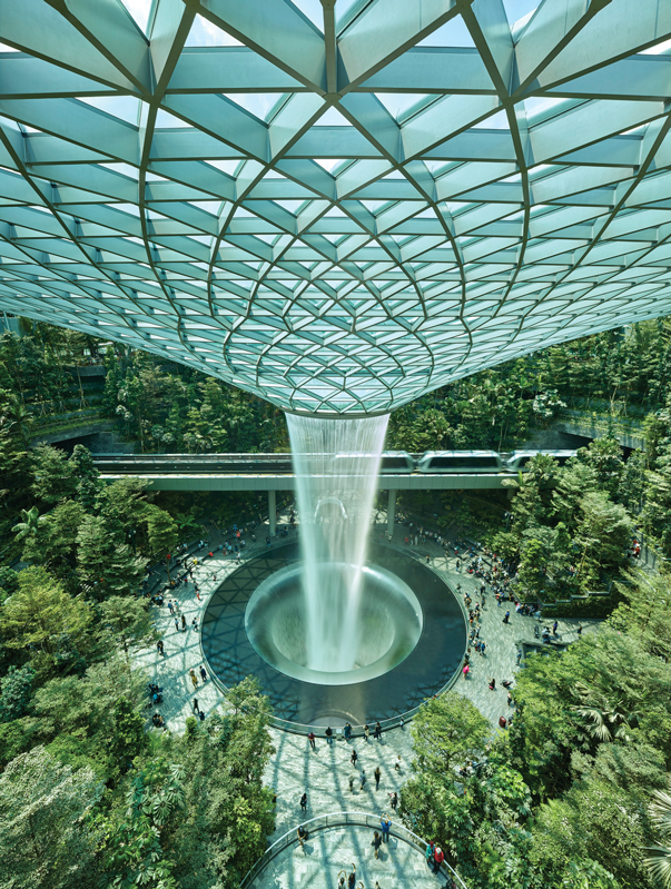
Completed structure.
The offset toroidal roof shape of the Jewel is the product of an elaborate architectural program that incorporated a forest valley, entrances to adjoining terminals at the gateway gardens, an indoor waterfall, and an oculus. The roof asymmetry and offset of the oculus were created to allow for the passage of the airport train through the project. The steel gridshell meets the base building at its 5th level where a steel ring beam circles the building, arching up at each of the gateway gardens. This ring beam allows for a uniform transition of the thrust and vertical forces from the springing of the gridshell into the base building.
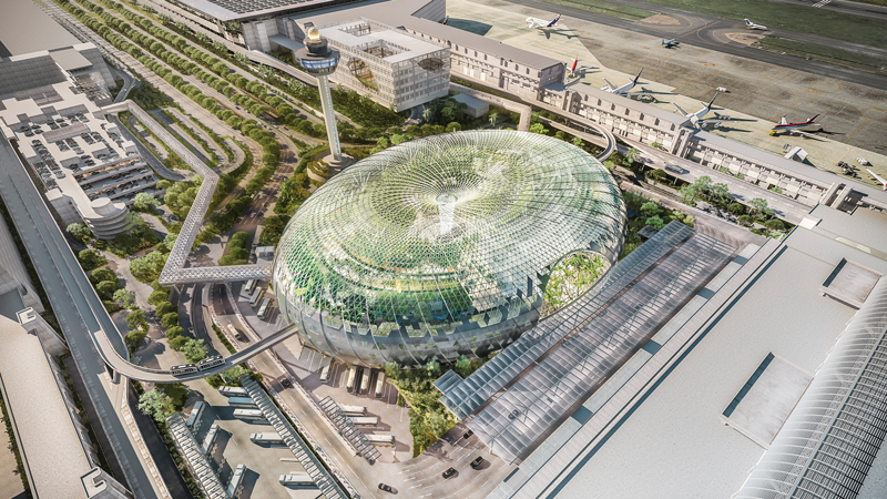
Aerial view of the exterior.
Traditional steel gridshells generally strive for thinness by resisting compression and tension forces only in the plane of the shell (with only modest bending capacity). This can be seen, for example, in the British Museum’s Great Court Roof.
The Jewel at Changi Airport goes beyond the traditional shell by accommodating not only the membrane forces in the shell but also the out-of-plane forces that bend the shell. To resist this combination of forces, the design team examined the forces in the shell and introduced deeper elements at locations subjected to bending, making the shell expressive of the forces flowing through the different zones.
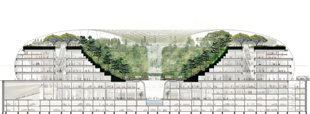
Building cross-section.
For example, the inner zone of the toroid moving from the internal support columns toward the oculus functions as a tension cone, with the waterfall and oculus suspended and pulling down on the structure. These membrane surface tensions act in two directions: hoop and meridional. With no risk of buckling and minimal bending, these steel elements are the shallowest in the project with only 8-inch depths.
In contrast, the outer section of the shell – between the perimeter support and moving toward the internal supports – has primarily compression hoop and meridional membrane forces with a force distribution similar to a dome. This area was designed for buckling and is made up of members 12 inches deep.
The most significant complexity is found in the zone around the intermediate supports. Here, the tension and compression fields that are pulling and pushing towards the center converge and are resisted by a compression ring zone. This is analogous to the spokes of a bicycle pulling inward and being resisted by the compression ring of the wheel rim. Also, the intermediate column supports of the shell in this ring create bending out of plane. Bending demands are highest here with very deep elements of up to 750mm (almost 30 inches) in the final constructed system.
In the end, this gridshell geometry with various shell depths creates a form that expresses the structural force patterns within the gridshell roof.
Using SAP2000 software, the engineering team experimented with varying the depths in the shell, rerunning analyses, and adding material where needed. These analyses included elastic as well as inelastic behavior. Buckling was addressed in an analysis that employed the provisions of the Eurocodes with Singapore amendments and was reviewed by the Singapore Building Authority as well as the Singapore EOR RSP-S.
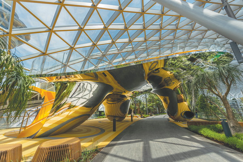
Discovery slides at canopy. Courtesy of Jewel Changi Airport.
As the design progressed, different shapes and discretizations were reviewed. The amount of information was very large, necessitating the development of an approach that could rapidly synthesize meaningful insights into the behavior of the structure. The team coined the phrase “big data” – referring not to structural analysis per se, but instead to the geometrical complexity of the form, the geometry of each connection, and the impact on fabrication and procurement. Taken together, it presented something beyond the typical scope of the structural engineer and required the involvement of other experts in the fields of computing, geometrical modeling, and mathematics. This allowed for an investigation into the methods of advanced fabrication and construction technology that would be required to build the project. It was possible to create a bid set of drawings and specifications that would allow enough definition of the quality of the work without restricting the improvements and changes to design that might be suggested by the specialty contractor.
Discretizing the Design
After resolving the overall form, the shape was discretized using triangular panels made of steel and glass. A series of horizontal hoop elements along the surface is overlaid by continuous bias or vertical elements, or both, to discretize the form as triangles. Larger triangles required larger steel elements, impacting the aesthetics. The project leaders traveled to visit gridshells in Europe and the United States to understand scale and to review similar triangulated forms in person and best understand how proportions and scale would affect the aesthetics and user experience. Another variable was the impact on procurement and manufacturing; the project leaders hoped for numerous competitive bids to reduce installed cost, resulting in the engineers recommending an upper-bound dimension on the triangle sizes.
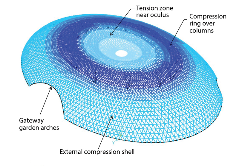
Sketch of distribution of the forces.
Also, as the continuous bias lines arch from the perimeter to the center, the triangles become progressively smaller, creating congestion and practical construction issues at the element intersections. The design team pruned the bias lines – removing elements as they got closer to the center, giving rise to different transitional geometries. This had a practical benefit, easing fabrication by keeping the scale of the triangles visually consistent. The flow of the surface design appears smooth and natural, and the transfer of forces is unimpeded. The steel elements present a consistent width throughout, though their depths are varied as required by the stress distribution, including at column intersections.
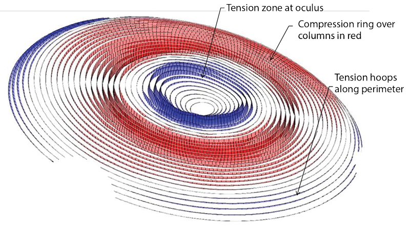
Stress diagram.
The project team defined and developed a precision steel node that was machine fabricated to connect sections of the diagrid roof system. Using mathematical analysis, the engineers developed standardized families of components to facilitate efficient fabrication and detailing, depending on the tolerances that might be possible to achieve in fabrication and detailing. In the end, based on the specialty contractor capability post-bid, unique nodes were found to be competitive and about 5,000 nodes and 14,000 steel elements, all unique, were produced to construct the toroidal shell assembly. The hardware elements all share a consistent geometrical ruleset so that their connection detailing is based on a consistent, project-wide system strategy.
Manufacturing processes available for this kind of work helped simplify the complexity of Jewel’s roof structure. All steel elements, for example, are straight, precisely cut from plate stock, and welded at angles by robots in Singapore’s steel manufacturer Yong-Nam shop. Many time zones away, in Germany, the company MERO employed a 3-D computer-numeric-controlled (CNC) milling machine to create nodes with stubs at the exact angles required to meet these connecting steel elements. On-site, one of five of the node-to-steel-piece connections are welded, and about 80% were pre-drilled with bolt holes. In China, the glass was fabricated, laminated, and assembled into panels, all cut from standard rectangular sheets based on a packing study by the engineers to optimize efficiency and reduce waste.
While the result offers a highly uniform and consistent appearance, the architect and the structural engineering team methodically tailored the enclosure to heighten the destination’s experience. The welcoming transparency of the gateway garden areas, for example, contrasts with the opaque metal panels used to define and express the lower levels. The glazing has been hardened at vehicle dropoff points for improved security and blast resilience. Glass fritting, which adds texture and opacity to the glass surfaces, helps reduce and finetune daylight transmission to allow optimal ultraviolet (UV) penetration for the garden areas while also helping to control solar heat gain for occupant comfort. The glass attachments were engineered to allow for the thinnest possible roof aesthetics, yet the nodes also integrate a durable system of flow-through gaskets and effective waterproofing, a dually redundant approach that helps ensure resistance to moisture leakage.
To ensure the final system would work as intended – and to facilitate assembly and erection processes – the project team created a 5-story visual mockup during the design phase. The visual mockup assisted in determining the level of workmanship required for various aspects of the enclosure. Also, several performance mockups were assembled to study waterproofing requirements; the testing of the mockups included spraying water and applying negative pressure inside of the performance specimens’ test chamber.
Construction and Review
Based on the design team’s analysis, BuroHappold suggested a construction sequence for the gridshell that began with the installation of the perimeter ring beam and support columns on the base building. This was to be followed by the building of the compression ring zone of the shell over the columns and then the sequential installation of pie-shaped wedges spanning between perimeter ring beam and compression ring. Last, the central oculus would be completed. The contractors Woh-Hup along with Yong-Nam and MERO, however, had a better idea. Based on their extensive experience and evaluation of the task ahead, they decided to begin with the oculus and then to assemble pie-shaped sections from oculus to perimeter ring beam using a moveable crash deck, which helped accommodate sequencing required for the construction of the base building.
Schematic of gridshell triangles.
The project received a Platinum rating from Singapore’s GreenMark program for environmentally sustainable buildings. Its integrated system of glazing, static and dynamic shading, and an innovative and efficient displacement ventilation system achieved the required high level of comfort for a diversity of activities, as well as the ability to sustain the vast array of plant life.
Safdie Architects’ vision, linked to advanced engineering analysis, state-of-the-art automated fabrication, precision manufacturing, and skilled on-site assembly methods, has created an unparalleled experience for world travelers and the people of Singapore. “Jewel weaves together an experience of nature and the marketplace, dramatically asserting the idea of the airport as an uplifting and vibrant urban center, engaging travelers, visitors, and residents, and echoing Singapore’s reputation as ‘The City in the Garden,’” says the architect, Moshe Safdie.
Designing with Big Data
As the design of this extensive gridshell project progressed to the review of different shapes and discretizations, the amount of information generated was considerable, necessitating a big data approach to rapidly synthesize meaningful insights into the design. The team called this big data, referring not to structural analysis, per se, but rather to the geometrical complexity of the form, the geometry of each connection, and the impact on fabrication and procurement.
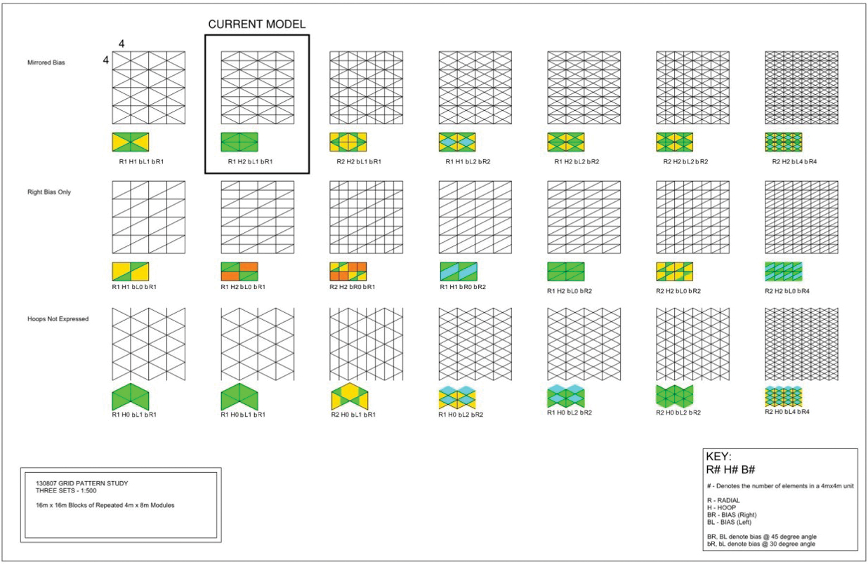
Layouts of discretized elements.
BuroHappold had very large datasets generated by different options that presented themselves and had to be evaluated and followed or cast aside. This is a natural and necessary development of today’s design flows where digital design has increased the speed at which options can be investigated. This represents an opportunity for structural engineers who understand the different drivers related to geometry and fabrication processes to take a renewed leadership position in the development and design of these sorts of projects.
The architectural program gave the initial geometries derived from the winning competition entry. Immediately, however, several questions needed to be answered:
- The form needs to work structurally. We can analyze this, but how do we make it better?
- How is the form to be discretized? In other words, where should there be structural elements?
- What is the appropriate size and geometry of the panels that will ultimately be defined?
Initially undertaken as straightforward structural exercises, these analyses quickly became informed by issues around fabrication – and limitations stemming from the maximum size of glass panels available for competitive bidding, the layout and sizes of the steel elements, and the type of nodal geometries. These answers tended to suggest specific strategies for the connections.
It quickly became clear that the manipulation of the structural models needed to be able to respond efficiently to the different drivers that had been identified. The construction of these models was based on the design surfaces that were generated in concert with the architect. These surfaces were then broken down into elements through the generation of construction lines based on surface curvature. The location and number of these lines were described based on ideas regarding the size and frequency of the panel sizes to be defined. This element discretization and panel sizing was a critical use of the datasets.
In the initial months of development when the focus of the project was primarily structural, a series of element patterns were investigated. These gave rise to several layouts that are part of the element discretization process and that had similar, but not identical, structural behavior. This included six- and eight-branch nodal configurations. The design eventually developed for competitive bidding was the six-branch design.
The generation of these models was based on the coordination of investigation-of-form options with Safdie Architects, and BuroHappold’s work consisted of interchanges of data using Rhino software. These files were then manipulated with written scripts in Grasshopper, created by BuroHappold, to generate geometrical files that both identified structural steel elements and could be imported into SAP2000 software for analysis. Elements were then sized in SAP2000 and reimported into a Rhino model for evaluation.
Eventually, the original Rhino files were used to create a 3-D extruded model in Revit that would be used as the basis for structural drawings. These models are extensive – they had approximately 14,000 elements, 5,000 nodes, and 10,000 total panels.
– Cristobal Correa, P.E., BuroHappold