
A Basic Primer
Fiber-reinforced polymer (FRP) composites are engineered to resist corrosion and provide high strength-to-weight and modulus-to-weight ratios compared to steel and concrete. In simplest terms, a composite material is produced when two or more substances are combined to take advantage of their unique strengths while overcoming their weaknesses. The first use of composite materials can be traced back to 1500 B.C. where Egyptians and Mesopotamians mixed mud and straw to create strong buildings. In the 1900s, the development of plastics birthed synthetic resins. Owens Corning introduced the first glass fiber combined with polymer resins. Following WWII, composites made their way into cars, airplanes, and boats, among other things.
When it comes to construction applications, FRP has mostly been confined to piping and tanks for corrosive environments. The last 15 years have seen this trend begin to shift along with the development of a modern polymer matrix material reinforced with fibers. Several factors have influenced these changes.
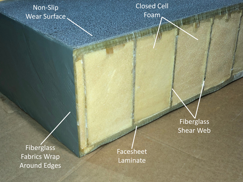
FRP cross-section.
Corroding concrete and steel, the need for lighter weight, shorter installation times, and reduced maintenance costs have prompted the adoption of FRP for mainstream infrastructure applications like bridges and bridge decks. Engineers tasked to select building materials have to make sure their choices will benefit construction and installation crews, as well as the end-user. The ability to mix the right combination of fiberglass fabric, core material, and resin means FRP products can be tailored to the requirements of individual bridge projects, for example.
Fiberglass and Carbon
Carbon fiber wrap is considered the standard choice for repairing steel and concrete structures because it provides high stiffness for applications that require bonding these materials together. In new bridge and bridge deck construction, carbon wrap does not deliver the same pay off because decks and bridges do not work compositely with steel and FRP components are prefabricated.

Fiberglass fabric is rolled out into the molding tool
in the required direction, and a Fiber-reinforced foam core is placed before vacuum infusion.
Engineers familiarizing themselves with composites are often asked to evaluate whether the reinforcing fiber for a project should be fiberglass or carbon. The reinforcement material for prefabricated FRP bridge elements is fiberglass. There is a big difference between fiberglass and carbon fiber in terms of properties and cost. For example, say you have a building in an earthquake zone that is held up by concrete columns. These columns are wrapped with carbon fiber to hold them in place. For a full bridge deck, the carbon cost would be prohibitive. Carbon fiber is roughly 15 times the cost of fiberglass FRP. In terms of weight, the difference between the two materials is minor. On an aircraft where weight is critical, the customer is willing to pay the higher cost for carbon fiber. However, for bridges and bridge decks, fiberglass composites are already five times lighter than conventional materials. Typically, owners are not willing to pay the higher price for carbon fiber when they are already getting significant weight savings with fiberglass FRP. So how does an engineer who is new to FRP begin the design process for a bridge or bridge deck application? Start with design requirements.
Design Requirements
Deck design loads are based on AASHTO LRFD Bridge Design Specification (6th Edition) and the LRFD Guide Specification for the Design of Pedestrian Bridges (Dec. 2009).
Typical pedestrian bridge deck requirements call for an unfactored uniform live load of 90 psf pedestrian loading. Midspan deflection is limited to the support span length divided by 500 (L/500). Vehicle maximum loading is rated at H-5 for a rear axle load of 8,000 pounds and a wheel load of 4,000 pounds to consider maintenance vehicles. Mid-span deflection under the vehicle is limited to L/300, and the mid-span deflection of a superstructure is limited to L/360. The uplift load is rated at 30 psf, with a minimum crushing strength of 150 psi.
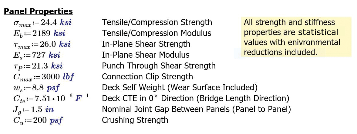
Example material properties determined during testing.
Although the supplier provides written specifications that define loads, an engineer also needs to think about how FRP will respond. Unlike concrete, engineers are not working from a standard base of design. In the case of FRP, agencies like the Department of Transportation (DOT) issue structural requirements while the FRP supplier submits plans on how to build it. The FRP supplier is also tasked with the requirement to show compliance and demonstrate that the material can handle loads with adequate safety factors. This is accomplished through design calculations and shop drawings.
For engineers who want to know how FRP is used compositely with steel, the answer is short and straightforward. The FRP supplier does not design for composite action. The stiffness and mass of the two materials are too different, and connection methods for composite action require tight tolerances. An FRP deck transfers the live loads to the support structure (steel beams or concrete piers), and the superstructure transfers the load to the ground.
There are other types of forces and stresses to consider, the largest being bolted connections. Wind shear is the other critical design criteria. Typically, wind uplift and seismic load are accounted for during the design phase for bridge and bridge deck connections. Wind shear is a component used to ensure a bridge or bridge deck’s safety factors are met.
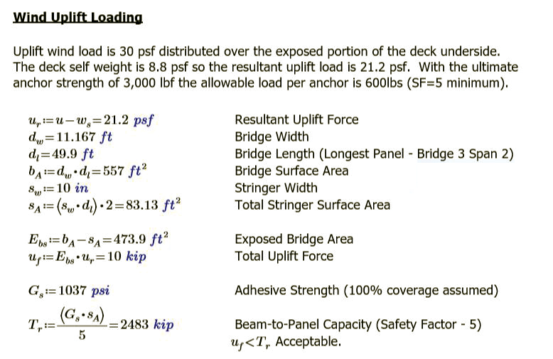
Example wind uplift and connection calculation.
Since FRP materials are linear elastic to failure and do not yield like steel, the strength safety factors for FRP need to be higher than steel. Safety factors on bending and shear capacity should be a minimum of 4 per AASHTO’s Guide Specification for Design of FRP Pedestrian Bridges. These safety factors are applied after statistical and environmental reductions. Since FRP has a lower stiffness than steel and reinforced concrete, deflection tends to drive the design of FRP panels and generates higher strength safety factors of more than 10.
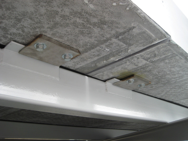
Connection holes are drilled and tapped in panels before shipping. On-site, the contractor screws the bolts through the clip plates to capture the steel superstructure.
Sandwich construction is used for FRP bridge decking because it provides the most efficient structural configuration for applications that require high stiffness and low weight. Multiple internal shear webs are molded with top and bottom face sheets to create a redundant pattern of “I-beams.” This anatomy is what allows panel depth and laminate thicknesses to be tailored to a project’s requirements while maintaining light weight.
The structural calculations used in traditional beam equations to generate a design’s overall safety factors starts with FRP properties and continues with strength.
It is important to remember that the physical properties of FRP structures can be directionalized based on a ‘rule of mixture’ approach. What you add in one direction takes away from the other. Almost all structures should have some fibers in the 0°, 45°, 90° or -45° directions. This provides basic fiber strength in all directions of a panel.
Standard test methods for FRP include ASTM D3039 for tensile strength and modulus; ASTM D6641 for compression strength and modulus; ASTM D7078 for in-plane shear testing; ASTM D732 for punch through shear testing; ASTM D5961 for pin bearing testing; ISO MAT-2209 for thermal expansion; and ASTM D5868 for adhesive lap shear.
Following material testing, other factors include material scatter that occurs during testing. To account for this, a statistical reduction factor based on ASTM D7290 is applied to strength values only, not to the modulus. Environmental reduction factors are then applied to account for long term exposure to saltwater, ultraviolet light, and thermal cycling. Since FRP does not show a decrease in properties even with high fatigue cycles, there are no reduction factors for fatigue loading. Bridge elements have been tested to 2,000,000 cycles. The resulting design properties are then carried forward into the calculations.
Design Calculations
The primary design calculations performed for FRP bridge decking include:
- Panel analysis for uniform and concentrated loadings
o Deflection
o Bending Stress
o Shear Stress
- Deck-to-support connection analysis
o Wind uplift
o Shear transfer between stringers
- Thermal expansion analysis
- Railing connection
Like traditional materials, engineers can calculate section properties and moment capacities with material design properties and geometry. The most complicated component of FRP deck design is determining effective deck width with concentrated or vehicle loading applied. There is no standard or rule of thumb for this because of the variations in deck design. The effective width can range from 40 to 90 percent of the support span. This variation is based on the internal structure of the FRP deck section. Unidirectional designs (in that they only have shear webs going in the primary load direction) tend to have effective widths closer to 40%, while bi-directional structures (in that they have shear webs in both directions) tend to have effective widths closer to 90%. There are two ways to determine the effective width of a design: FEA analysis or full-scale testing.
Deflection is another critical design requirement for FRP decks. The design engineer must properly account for the loading and span conditions and verify that calculated deflections fall within project specifications.
Connections
Generally, FRP decks are joined to superstructure supports using mechanically fastened clips that capture the underside of the beam flange. This type of connection restrains the deck for vertical loads, both live and wind uplift, while allowing for construction tolerances and thermal expansion variables. This connection does not provide composite action of the deck and beams as typically happens with concrete decking. The mass of the FRP is so low that it is not worth using a more complicated and costly connection detail to gain only a slight benefit of composite action.
An FRP fabricator should design for mechanical connections analytically but test for capacity. Clips are sized for compaction against the beam flange. Steel plates are embedded in the deck to receive the bolts and handle the concentrated loads.
The light weight of FRP decking makes certain calculations more critical. The uplift load determines the number of connections needed to keep the deck attached. Seismic and vibration concerns are less critical because of the material’s light weight.
Sandwich construction means that compression (crushing) loads and shear loads from concentrated loads must be evaluated. Concentrated loads are typically vehicle loads generated by a vehicle or truck’s wheels on the bridge. In the case of a pedestrian span, compression or crushing load could refer to a maintenance vehicle. Wider pedestrian bridges must handle either maintenance vehicles or emergency vehicles.
When it comes to crushing capacity, one option is to design for a 4,000-pound wheel load over a 10-inch by 10-inch wheel area, for 40 psi crushing force. The engineer then specifies a panel with a 160-psi crushing strength for a 4 times factor of safety.
FRP bridge decks (and other elements) can be modified in the field. Threaded holes can be tapped, or holes can be drilled, and pieces cut. Upfront engineering coordination and prefabrication minimizes the potential for field issues. It is another advantage of working with FRP. Prefabrication saves the owner and contractor time and money.■