
Part 5: Foundations
Spread Footings
Flexural Reinforcement
Requirements for the distribution of flexural reinforcement in two-way footings are given in Sections 13.3.2.2 and 13.3.3.3 of ACI 318-14, Building Code Requirements for Structural Concrete. For square footings, the reinforcement is to be distributed uniformly across the entire width of the footing in both directions. In the case of rectangular footings, the reinforcement must be distributed in accordance with the requirements in Section 13.3.3.3 of ACI 318-14, which are illustrated in Figure 1. Reinforcement in the long direction is uniformly distributed across the entire width. A portion of the reinforcement in the short direction is uniformly banded over the column with the remainder uniformly distributed outside of the band width.
To facilitate bar placement in the field, a common practice is to increase the amount of reinforcement in the short direction by 2β/(β+1) (where β is the ratio of the long side to the short side of the footing) and space it uniformly across the long dimension of the footing instead of distributing the bars as shown in Figure 1.
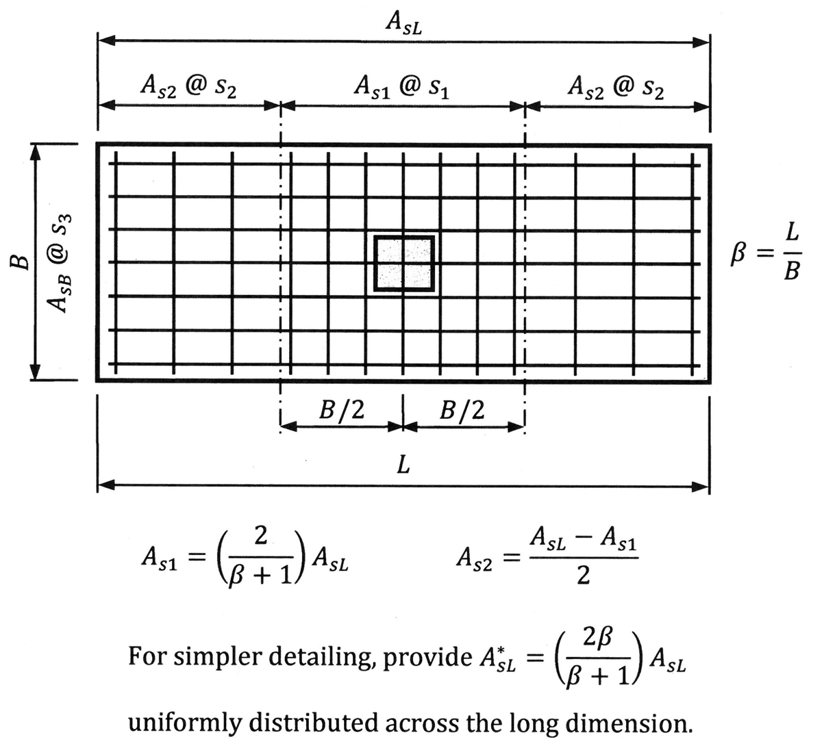
Figure 1. Distribution of flexural reinforcement in a rectangular footing.
Reinforcement Across the Interface
The amount of reinforcement that is required at the interface between a column or wall and the footing depends on the type of stress in the longitudinal bars of the supported member under all applicable load combinations.
Dowels are commonly used as interface reinforcement between columns or walls and footings. The dowels are set in the footing prior to casting the footing concrete and are subsequently spliced to the longitudinal bars in the column or wall.
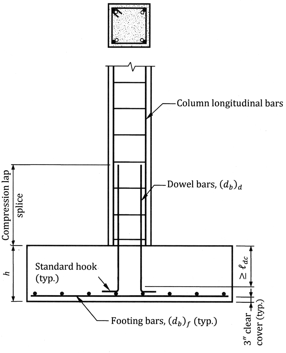
Figure 2. Dowel bars where all the longitudinal bars in the column are in compression.
Illustrated in Figure 2 are dowels across the interface between a column and footing. For the case where all the column bars are in compression, the dowels must extend into the footing a compression development length ldc determined in accordance with Section 25.4.9.2 of ACI 318-14. The dowel bars are usually hooked and extend to the level of the flexural reinforcement in the footing. According to Section 25.4.1.2 of ACI 318-14, the hooked portion of the dowels cannot be considered effective for developing the dowel bars in compression. The following equation must be satisfied to ensure adequate development of the dowels in the footing:
h ≥ ldc + r + (db)dowel + 2(db)f + cover
In this equation, r is the radius of the dowel bar bend, (db)dowel is the diameter of the dowel bars, and (db)f is the diameter of the flexural reinforcement.
Tensile forces (either direct or transferred by a moment) must be resisted entirely by reinforcement across the interface. Tensile anchorage of the dowel bars into a footing is typically accomplished by providing 90-degree standard hooks at the ends of the dowel bars with the development length of the hooked bar, ldh, determined in accordance with Section 25.4.3 of ACI 318-14 (Figure 3).
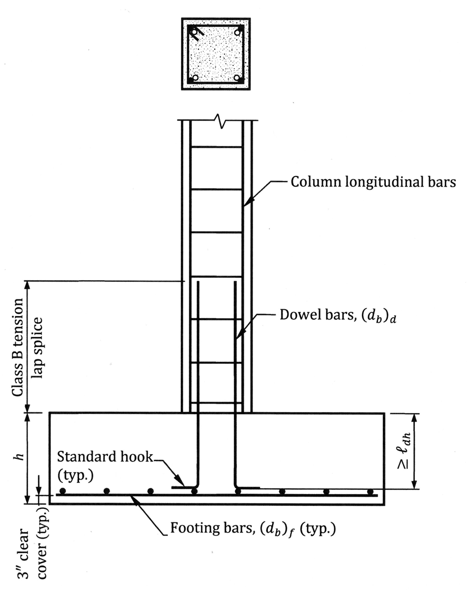
Figure 3. Dowel bars where the longitudinal bars in the column are in tension.
The location of the dowels protruding from a footing can have an impact on the installation of preassembled column cages. Dowels should be positioned so as not to interfere with the longitudinal bars or the tie hooks in the column.
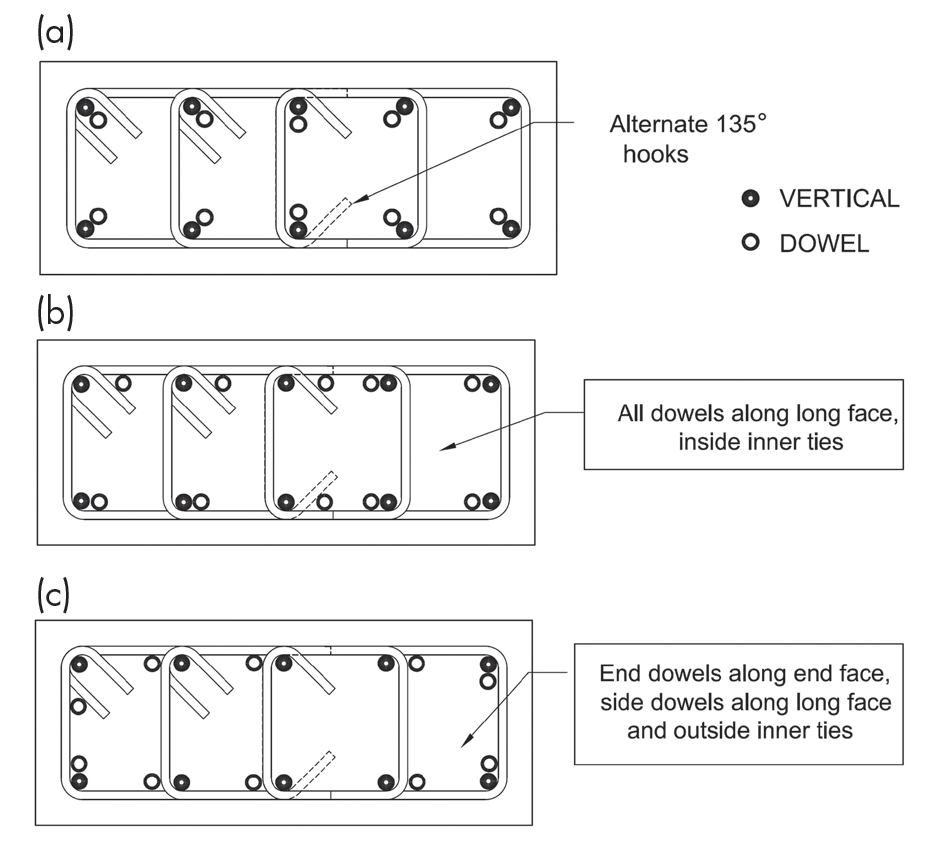
Figure 4. a) Ideal arrangement of dowels; b) Dowels arranged on the long face of column; c) Least preferable arrangement of dowels.
Consider the arrangements of the column longitudinal bars and the dowel bars depicted in Figure 4a. Except for the bars located adjacent to the center crosstie, the dowel bars are offset 45 degrees from the column’s longitudinal bars relative to the long side of the column. There is no interference between the dowel bars and the 135-degree tie hooks in this arrangement. At the center crosstie, the dowel bars are located 90 degrees inboard relative to the long side of the column so that no interference occurs between them and the hooks of the crosstie. Depicted in Figure 4b is the same column but, in this case, all the dowel bars are adjacent to the tie on the long side of the column. This arrangement is not as preferable as the one in Figure 4a; however, it is manageable because the ends of the hooks are relatively flexible and can be maneuvered around the dowels. Some of the dowel bars in Figure 4c are located on the long face of the column and some on the short face. This is the least preferable arrangement because there is more potential for difficulties during installation; lowering the column cage over the dowels will be challenging because the ties will not allow the same degree of flexibility as will the hooks at the ends of ties.
Mat Foundations
Once the thickness of a mat foundation has been established and the required amounts of reinforcement are calculated at the critical sections, a suitable bar size and spacing must be selected.
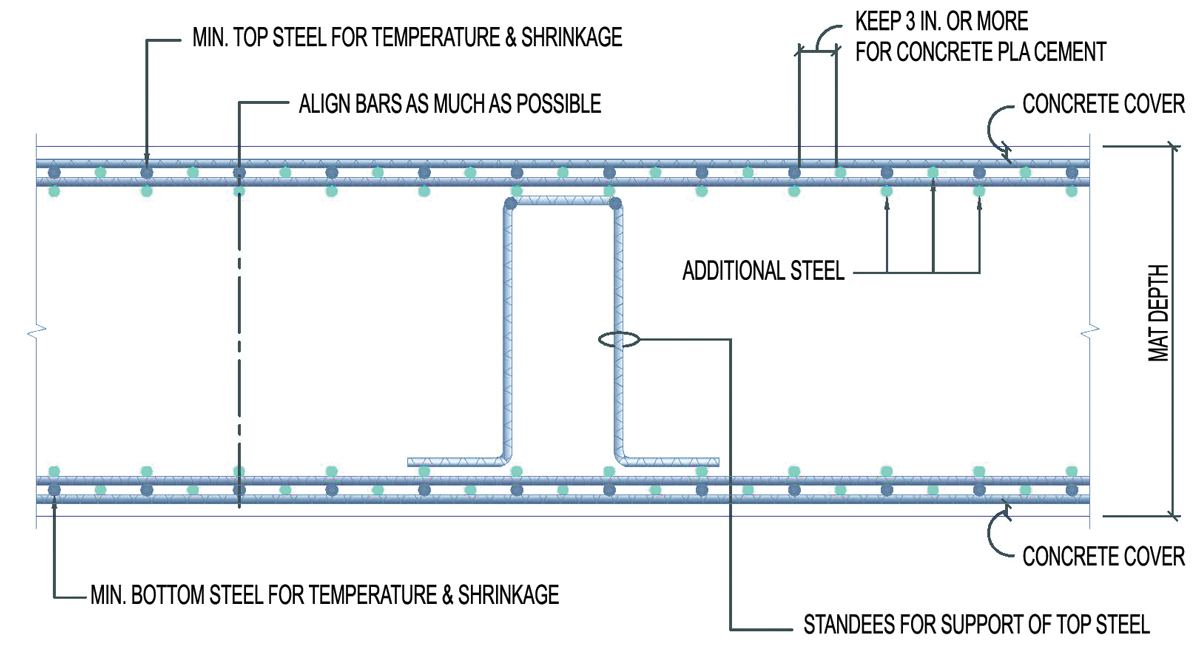
Figure 5. Typical reinforcement configuration in a deep mat foundation.
For deep mats, the reinforcing bars can be placed in two layers at both the top and bottom faces or in four layers. Bars that are in the interior layers should be aligned with those in the outer layer (Figure 5). This helps reduce voids in the concrete because it provides a clear passage for concrete placement.
The size of the bars in the interior layers should be the same size as, or smaller than, the bars in the outer layers. It is recommended that a 3-inch spacing be provided between the bars to facilitate concrete placement.
In cases where additional bars are required in localized areas that are heavily loaded, these bars should be spaced as a multiple or sub-multiple of the spacing for the typical flexural reinforcement.
Where the column spacing is not on a regular, symmetric grid, the layout of the reinforcing bars in the mat should be placed on an orthogonal grid and should not be skewed to follow the column layout. Additional bars can be placed at locations in the regular grid wherever required. This dramatically simplifies placing the bars in the field.
Staggered splices should be avoided because of their negative impact on placement and constructability. Using the maximum straight bar length as often as possible usually minimizes the number of lap splices.
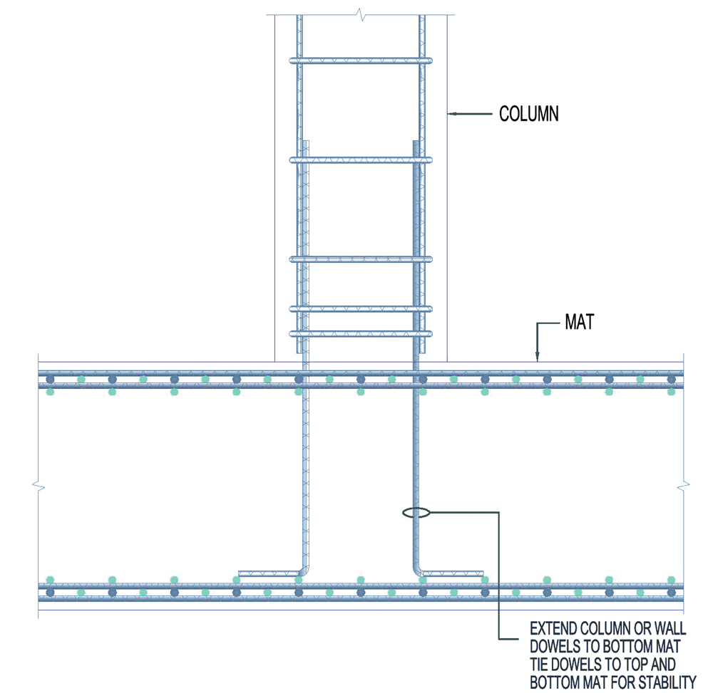
Figure 6. Dowels in a mat foundation.
Like columns supported by spread footings, the dowels from the columns and walls that are supported by the mat should extend to the bottom layer of flexural reinforcement in the mat (Figure 6). The dowels should have a 90-degree standard hook at the bottom end; this allows the dowels to be tied to both the top and bottom layers of reinforcement in the mat, which secures the dowels from displacing before or during concrete placement.
Drilled Piers
Recommended reinforcement details for drilled piers subjected to uniaxial compression loads are given in Figure 7. A minimum longitudinal reinforcement ratio of 0.005 should be provided; this corresponds to the ratio that is permitted in Section 10.3.1.2 of ACI 318-14 for columns with cross-sections that are larger than required for the applied loads.
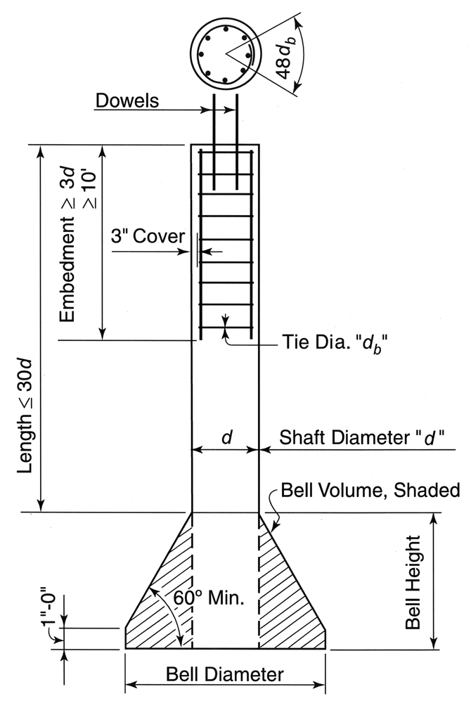
Figure 7. Reinforcement details for drilled piers subjected to axial compression loads.
Grade Beams
A unique challenge occurs at the grade beam/drilled pier joint. If a grade beam is too shallow, congestion problems can occur at the joints. Some of the options to alleviate this problem are:
- Extend the column dowels directly into the drilled pier
- Provide a deeper grade beam
- Provide a deeper grade beam only at the drilled pier
- Provide a pile cap under the grade beam at the drilled pier
- Hold back the concrete from the pile top
- Provide a blockout at the top of the drilled pier
One or more of these options may not be viable in every situation, and there may be other options not listed that may be more suitable for the situation at hand. Option 2 is illustrated in Figure 8.
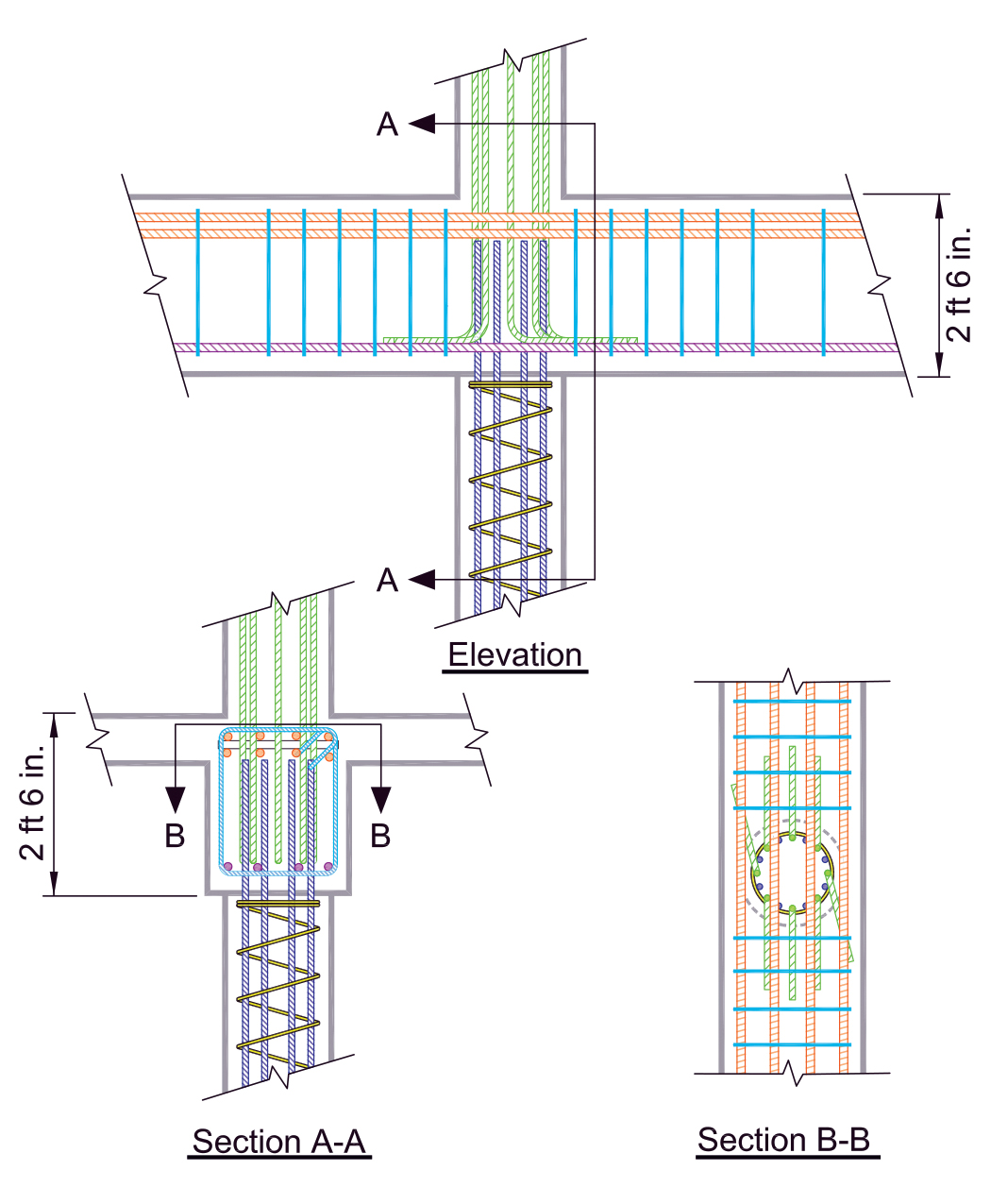
Figure 8. Option 2 – Providing a deeper grade beam at a grade beam-drilled pier joint.
More information on economical detailing of foundations can be found in the CRSI publications Design Guide for Economical Reinforced Concrete Structures, Design Guide for Drilled Piers, and Design and Detailing of Low-Rise Reinforced Concrete Buildings. Design and detailing requirements for pile caps can be found in Design Guide for Pile Caps and Design Guide for AASHTO Pile Caps.■
References
ACI (American Concrete Institute). 2014. Building Code Requirements for Structural Concrete and Commentary. ACI 318-14, Farmington Hills, Michigan.
CRSI (Concrete Reinforcing Steel Institute). 2015. Design Guide for Pile Caps. Schaumburg, IL.
CRSI (Concrete Reinforcing Steel Institute). 2016. Design Guide for Economical Reinforced Concrete Structures. Schaumburg, IL.
CRSI (Concrete Reinforcing Steel Institute). 2016. Design Guide for Drilled Piers. Schaumburg, IL.
CRSI (Concrete Reinforcing Steel Institute). 2017. Design and Detailing of Low-Rise Reinforced Concrete Buildings. Schaumburg, IL.
CRSI (Concrete Reinforcing Steel Institute). 2018. Design Guide for AASHTO Pile Caps. Schaumburg, IL.