
The thermal factor, Ct, in the American Society of Civil Engineers’ Minimum Design Loads for Buildings and Other Structures, ASCE 7-16, is intended to account for expected changes in roof snow loads due to heat flow through the roof. As one might expect, for poorly insulated structures with large amounts of thermal energy available to melt roof snow, the Ct factor is low (Ct = 0.85 for certain greenhouses) while, for very well insulated structures, the Ct factor is high (Ct = 1.30 for freezer buildings). For more common structures, the Ct factors in ASCE 7-16’s Table 7.3-2 are 1.1 and 1.2 for cold roofs and unheated structures, respectively. In relation to Table 7.3-2, cold roofs are those with an air passageway (typically inflow at the eave and outflow at a ridge vent) between the insulation layer below and the roofing material layer above. Finally, for the remaining heated structures (i.e., all structures except as indicated above), Ct = 1.0.
These thermal factor values are based upon observations and engineering judgment. In relation to the observation, there are two available databases of simultaneous ground snow and roof snow load measurements. The first is a result of a United States Army Corps of Engineers’ Cold Regions Research and Engineering Laboratory (CRREL) project in the early 1980s while the second is a more extensive measurement program by the Agriculture University of Norway. Unfortunately, the Norwegian study involved unheated structures only and, hence, does not provide useful comparative information on the thermal factor. In the CRREL project, the structures were characterized as either heated or unheated. The ratio of roof-to-ground snow load for the heated structures averaged 0.54, while the average for the unheated structures was 0.67. Hence, the CRREL observations are reasonably consistent with the thermal factor of 1.2 for unheated structures in comparison to Ct = 1.0 for heated structures, since 0.67/0.54 = 1.24. The Ct = 1.3 value proscribed in ASCE 7 for freezer buildings was an outgrowth of observation in a Structural Engineers Association of Washington (SEAW) report on snow-related structural collapse in the Pacific Northwest during the winter of 1997-1998. Roof snow loads on freezer buildings, absent drifting or sliding, were observed to be larger than the corresponding ground snow load. Since the roof and ground in the Pacific Northeast were subject to nominally the same snowfall from above, the difference has been attributed to more ground snow melting over time due to the “warm” earth below, than roof snow melting due to the freezer space below.
The ASCE 7 thermal factors seem reasonably consistent with the limited available measurements. Until recently, these factors have not generated many comments or complaints from practitioners. However, federal agencies are now requiring (or “are recommending”) increased amounts of roof insulation for certain structural retrofit situations. The laudable goal of such new requirements is improvements in a building’s energy efficiency. However, requiring increases in roof insulation raises questions regarding possible corresponding increases in roof snow loads. That is, a building that was properly classified as a heated structure, with Ct = 1.0, may morph into the equivalent of an unheated structure with Ct = 1.2 due to increases in roof insulation.
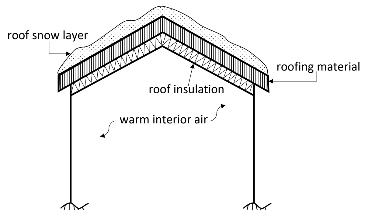
Figure 1. Cathedral ceiling model considered by O’Rourke et al. (2010).
Clearly, the available measurement-based databases which do not provide the roof insulation level (i.e., R or U, see later in this article for definitions) cannot be used to address the increased insulation question. However, for a class of buildings, analytical estimates of expected eave ice dam size can be used to investigate the influence of increased roof insulation upon the thermal factor Ct. O’Rourke et al. (2010) (hereafter referred to as the OGT paper) considered a cathedral ceiling structure, sketched in Figure 1, with no air passageway located in the insulation and roofing material layers between the heated interior air space below and the roof snow layer above. As such, the building would be considered as having a warm roof with Ct = 1.0. For a building with an attic, the Ct = 1.0 warm roof classification would also apply, if the attic is unvented and there is no air passageway between the roof insulation layer and the roofing materials layer, as sketched in Figure 2. In terms of the interior to exterior heat flow through the roof, the cathedral ceiling in Figure 1 behaves the same as the warm attic in Figure 2 if, as assumed herein, the warm interior air temperature (Figure 1) is the same as the warm attic air temperature (Figure 2). Herein, for simplicity, both roofs sketched in Figures 1 and 2 will be referred to as “warm-unvented attic” structures.
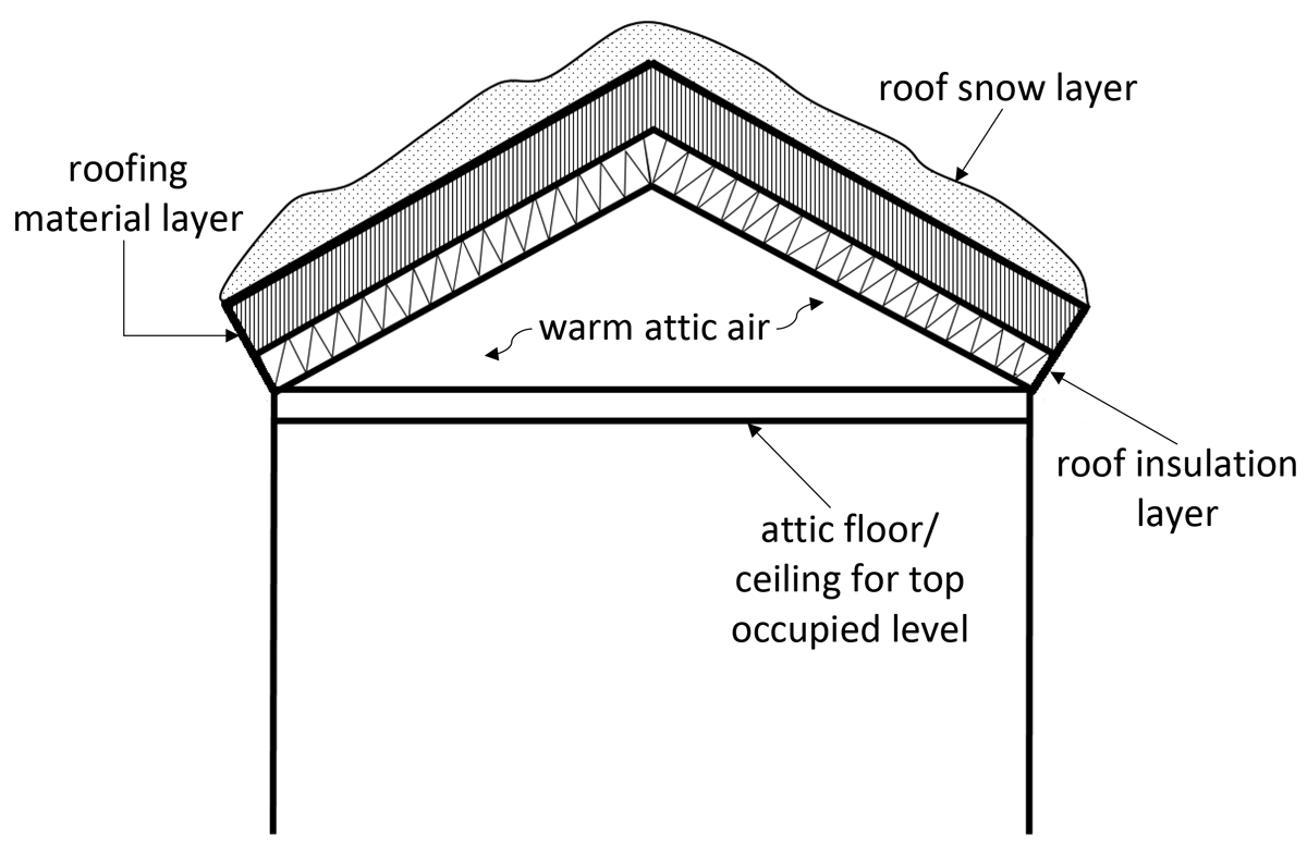
Figure 2. Warm-unvented attic mode.
Note that if the cathedral ceiling structure sketched in Figure 1 had an air passage space between the roof insulation layer below and the roofing material layer above, it would correctly be classified as a cold roof with Ct = 1.1. Similarly, if the structure sketched in Figure 2 had a vented attic with the insulation layer in the attic floor, it also would be considered as having a cold roof with Ct = 1.1. Herein, again for simplicity, both these Ct = 1.1 structures will be referred to as “cold-vented attic” structures.
In relation to the melting of roof snow, determining the heat flow through the warm-unvented attic structures is straight forward. All the thermal energy flowing upwards goes through the insulation layer and then the roof snow layer. However, for the cold-vented attic structure, some of the thermal energy is carried by air flow out through the vents (air passageways) while the rest flows up through the snow layer. The melting of roof snow on cold-vented attic buildings is due solely to the portion of the thermal energy which flows through the rooftop snow layer. Since the OGT paper considered only warm, unvented attic buildings, the retrofitted roof Ct values suggested herein are only for warm, unvented attic buildings sketched in Figures 1 and 2, that is buildings initially classified as Ct = 1.0.
Recommended Thermal Factors
The purpose of the OGT paper was to estimate the physical size of eave ice dams so that informed provisions for the horizontal extent of various “snow and ice guard” products could be determined. Such eave ice dams form when the outdoor temperature is below freezing and the bottom of the roof snow layer is 32°F. For these conditions, meltwater at the bottom of the roof snow layer forms, some of it flowing downslope to the eave and refreezing into the eave ice dam. As such, the size of the eave ice dam can be used to back-calculate the amount of roof snow “lost” to roof-related thermal effects.
Note that these losses are due to thermal energy flowing from the interior of a heated, unvented attic to the exterior during times when the exterior temperature is below freezing. Such ice-dam-related thermal losses are unrelated to the loss of roof snow due to solar radiation effects, or above freezing exterior temperature. It should be mentioned that solar radiation and above freezing exterior temperature also reduce the ground snow load as well as the roof snow load atop unheated buildings.
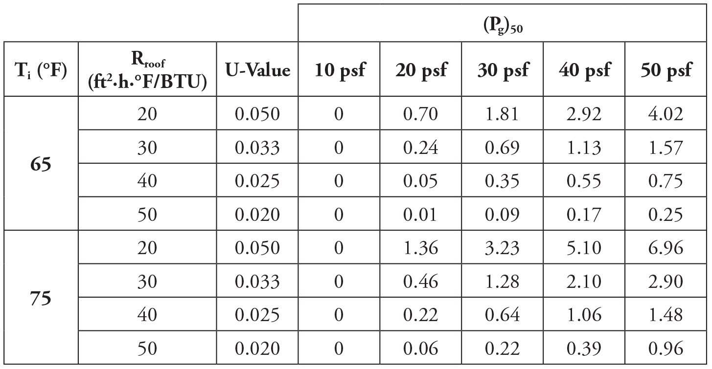
Table 1. Roof snow reduction (psf) due to thermal effects, 20-year MRI.
Table 8 in the 2010 OGT paper presents the horizontal extent of the 20-year Mean Recurrence Interval (MRI) eave ice dam, as a function of the indoor temperature Ti, the roof R-value Rroof (a measure of resistance to heat transfer), the roof U-value (a measure of heat transfer = 1/R), the roof slope, and the 50-year ground snow load Pg. The tabulated values are for a roof with a horizontal eave-to-ridge distance of 80 feet. It is a simple matter to convert the horizontal extent values into the corresponding reduction in roof snow load due to the aforementioned eave ice dam, again with a 20-year MRI. These estimated reductions in the 20-year MRI roof snow load due to thermal effects are presented in Table 1.
Notice that wetting of interior surfaces due to eave ice dams was considered to be a serviceability issue. As such, a 20-year MRI value for the horizontal extent of an ice and snow guard product was thought to be appropriate. However, for structural loads due to snow (a strength issue), a 50-year MRI value is desired. This “mismatch” of return periods is addressed below by calculating the Ct for a 20-year ground and roof load, and assuming the Ct would normally be the same for the case of a 50-year ground and roof loads.
As one would expect, the thermal losses in Table 1 are larger for an indoor temperature of 75°F than for an indoor temperature of 65°F. Similarly, the losses are larger for a roof R-value, Rroof, of 20 in comparison to those for Rroof = 50.
The losses for a location with (Pg)50 = 10 psf are zero for both Ti = 65°F and Ti = 75°F and Rroof between 20 and 50. For such locations, the thermal resistance of the roof snow layer is quite small and the thermal resistance of the insulation layer is comparatively large. As a result, the location of the melting point (temperature = 32°F) is in the insulation layer. No meltwater is generated at the base of the roof snow layer, and there is no eave ice dam formation.
As noted above, the thermal losses in Table 1 are for a 20-year MRI winter. For consistency, they need to be compared to the 20-year MRI roof snow load, which requires the 20-year MRI ground snow load. The commentary of ASCE 7-16 (specifically Table C7.2-3) provides factors for converting the 50-year MRI ground snow loads into other return periods. Interpolated from the tabulated factors,
(Pg)20 = 0.77 (Pg)50 (Eqn. 1)
The 20-year roof snow load for an unheated building (Ct = 1.2) becomes
(Pr)20, unheated = 0.7CeCsIs(1.2)(Pg)20 (Eqn. 2)
While the 20-year roof snow load for a heated building with a yet to be determined Ct is
(Pr)20, heated = 0.7CeCsIs(Ct)(Pg)20 (Eqn. 3)
However, the difference is simply the thermal losses in Table 1, or
(Pr)20, heated = (Pr)20, unheated – Table 1 Value (Eqn. 4)
Hence, the thermal factor for a warm, unvented attic building based upon a 20-year MRI becomes
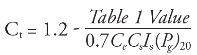
As noted above, it is assumed that the thermal factor for a 20-year MRI ground snow and a 20-year MRI roof snow load (as given in Equation 5) also applies to the desired case of 50-year MRI ground and roof loads.
The Ct value from Equation 5 was determined for all the cells in Table 1, for Ce = Cs = Is = 1.0. The values for Ti = 65°F and 75°F were then averaged. The resulting “calculated” thermal factors are presented in Table 2.
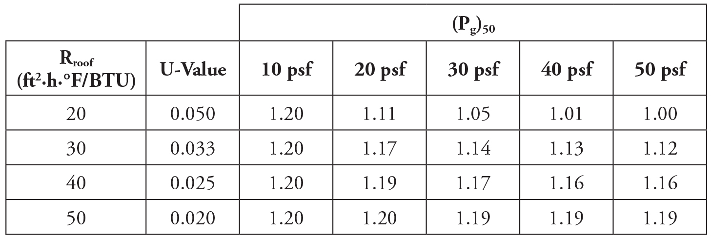
Table 2. Recommended ASCE 7 Thermal Factor, Ct, for a warm, unvented attic structure as a function of the 50-year MRI ground snow load, (Pg)50, and the roof R-value, Rroof.
Note, for the ground snow regions considered, ranging from 10 psf (e.g., Nashville, TN) to 50 psf (e.g., Minneapolis MN), an Rroof = 50 roof provides enough insulation that it behaves like an unheated structure. Also, for a location with (Pg)50 = 10 psf, (such as Nashville) a roof R-value of 20 or more provides enough roof insulation that it behaves like a Ct = 1.2 unheated structure. Conversely, for a location with (Pg)50 = 50 psf (such as Minneapolis), an Rroof = 20 roof behaves like an ordinary Ct = 1.0 heated structure.
Conclusion
Over time, building energy efficiency, in general, and roof insulation requirements in particular, have been increasing. Specifically, very well insulated roofs for heated buildings may now behave thermally like an unheated building. Hence, the current simplified categories of “heated” or “unheated” for the ASCE 7 thermal factors are no longer adequate.
Based upon prior eave ice dam research on roof snow losses due to thermal effects, the authors have developed recommended thermal factor values as a function of the ground snow load and the amount of roof insulation. The recommended Ct values are for heated buildings with unvented roofs. They are expected to be particularly useful in situations where an existing building retrofit includes increased roof insulation.■
References
O’Rourke, M., Ganguly, M., and Thompson, (2010), “Eave Ice Dams,” J. Architectural Engineering, ASCE Vol.16, No. I, 9 Pages.