
As structural engineers engaged in forensic investigations of failed structures, the authors have encountered concrete foundation walls at residential and retail facilities that have failed as the result of lateral soil pressure. In many instances, the walls are primarily reinforced with vertically oriented rebar with nominal horizontal steel, implying that the top of the wall is supported laterally by the framed floor system.
The 2012 International Residential Code (IRC) recognizes the distinction of a wall supported laterally at the top and one that is not. Section R404.1.2.2 provides prescriptive requirements for horizontal and vertical reinforcement for concrete walls laterally supported at the top and bottom. Minimum reinforcement requirements are contained in tables R404.1.2(1) through R404.1.2(8). Section R404.1.2.2.2 addresses walls that are not laterally supported at the top and refers to section R404.1.3 which requires that the walls be designed in accordance with accepted engineering practice. Subsequently, the question arises as to what constitutes lateral support at the top of the wall?
It is the purpose of this article to outline the procedures for adequately designing concrete foundation walls subjected to lateral soil pressure. Included are charts and graphs to assist in the design of structural systems with and without the wall laterally supported at the top.
Background
Typical residential construction consists of a 2x wood sill plate bolted to the top of the foundation. Where floor joists are parallel to the wall without continuous periodic blocking between joists, no lateral support is provided at the top of the wall. For joists perpendicular to the wall, lateral forces at the top of the wall must first be transferred from the wall to the sill plate via anchor bolts, from the sill plate into the floor joists via toe nails, and subsequently into the floor diaphragm.
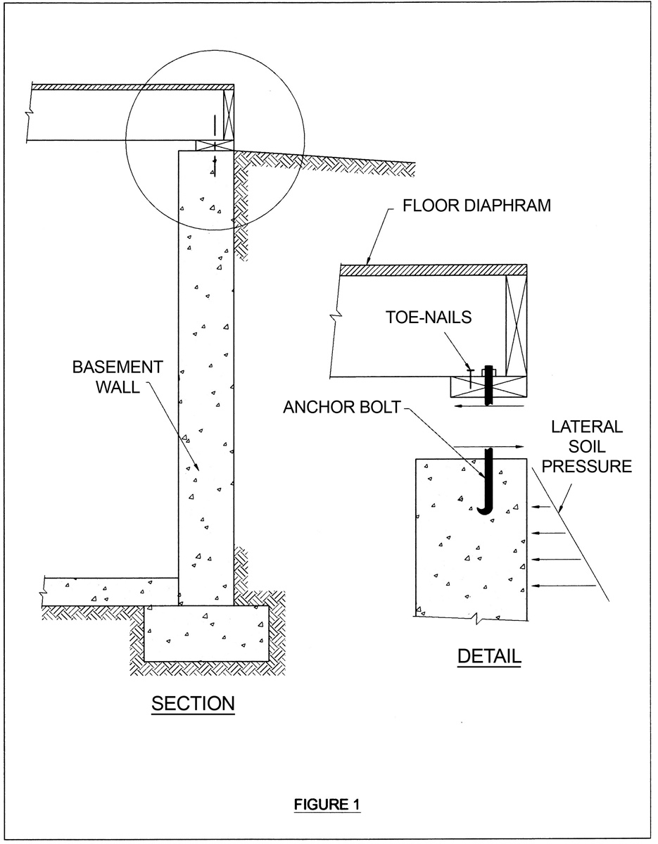
Figure 1. Example of typical wall construction.
An example of typical basement wall construction laterally supported at the top is illustrated in Figure 1 and will be evaluated as noted in Figure 2. Regardless of the type of construction utilized at the top of the wall, the methodology presented would apply to any construction detail at the top of the wall. The detail must be capable of transferring the wall lateral pressure into the floor diaphragm.
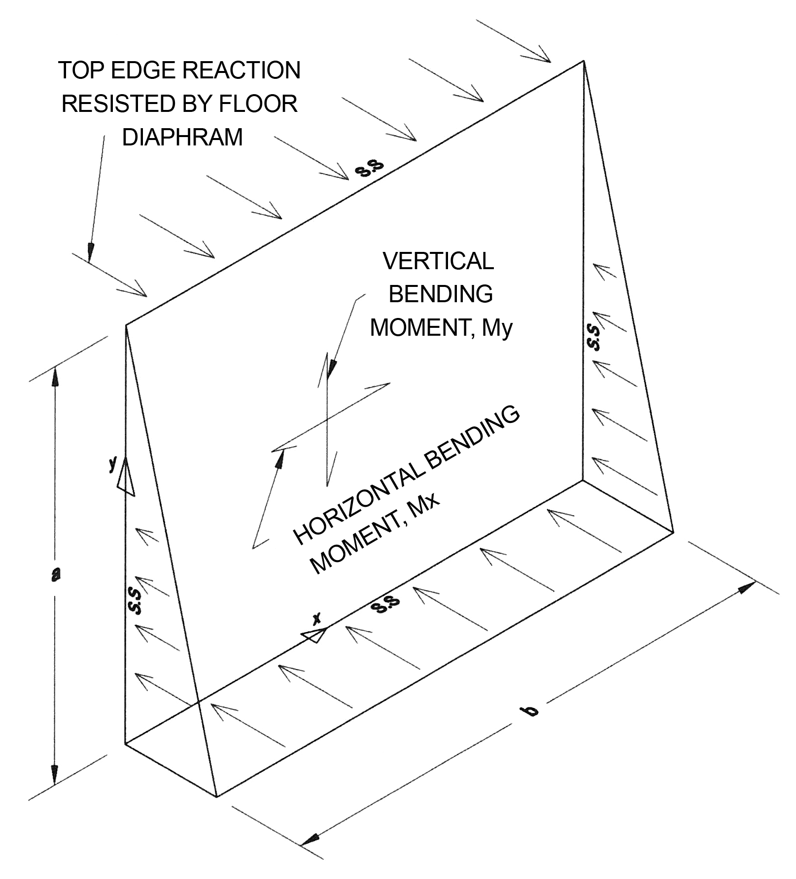
Figure 2. Flat plate subjected to equivalent fluid pressure (EFP).
While numerous solutions exist for rectangular plates subjected to equivalent hydrostatic pressure (Timoshenko, et.al., and Portland Cement Association Document ST 63), the authors have found that the use of a commercially available finite element program provides the results necessary to determine the reactions at the top of the foundation and the resultant bending moments.
A comparison was made of the results of the FEM method and those contained in the Portland Cement Association (PCA) document to verify the validity of the FEM computer model. To evaluate the effects of various elements, three sizes were considered: 12- x 12-inch,
6- x 6-inch and 3- x 3-inch. The plate considered is 16 feet long by 8 feet high, 8 inches thick and free at the top, pinned at the base, and fixed at the vertical edges. The resulting moments are as shown in Table 1.
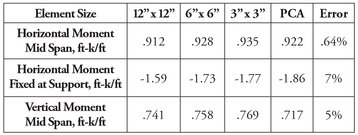
Table 1. FEM method results compared to PAC-ST 63.
Utilization of an element size of 6 inches x 6 inches results in a difference of approximately 5 to 7% when compared to the PCA results. It is recommended that a 6- x 6-inch element size adequately defines the results.
Graphs were developed for various wall boundary conditions based on an element size of 6 inches x 6 inches to facilitate the design of the walls subjected to lateral soil pressure. Figure 3 represents a plate simply supported on all four sides subjected to an equivalent fluid pressure (EFP). Figure 3 provides the reaction at the top of the wall to evaluate if the connection of the top of the wall is adequate to transfer the reaction into the floor diaphragm.
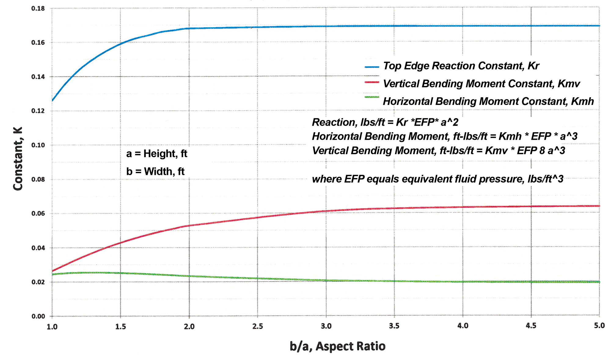
Figure 3. Plate simply supported on four sides.
For walls with an aspect ratio of horizontal span to wall height of two and greater, one can determine the horizontal reaction at the top of the wall by treating it as a simply supported beam. Aspect ratios less than two can be analyzed utilizing Figure 3. With aspect ratios greater than three, the vertical bending moments can be determined by treating the wall as a simply supported beam spanning from top to bottom. Less than three, one can utilize Figure 3 to determine the vertical bending moments.
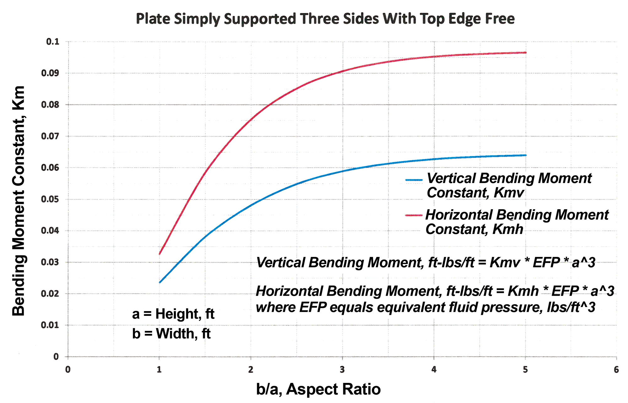
Figure 4. Plate simply supported on three sides with top edge free.
If it is determined that the detail at the top of the wall cannot be economically designed to accommodate the reactive forces, then the wall must be treated as a plate with the top edge free. Figure 4 represents a plate free at the top and simply supported on the remaining three sides. Figure 5 and 6 represent a plate simply supported at the base, top edge free, and vertical sides fixed.
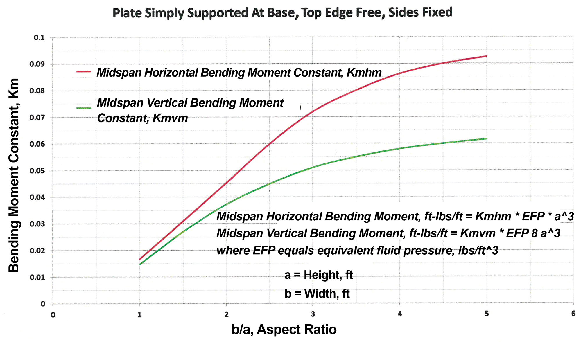
Figure 5. Plate simply supported at base, top edge free, sides fixed.
It should be recognized that typical foundations do not consist of a single flat plate but several plates forming a box section. Consequently, the conditions at the vertical edges cannot be represented as being pinned or totally fixed. If the length of the walls at the supports are equal and perpendicular to the wall in question, the supports can be fixed provided the wall pressure is equal on all sides.
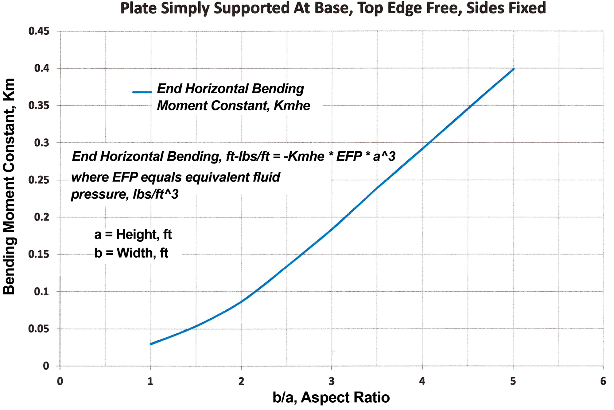
Figure 6. Plate simply supported at base, top edge free, sides fixed.
In some cases, however, the designer may choose to conservatively assume simply supported conditions at the vertical edges to calculate the horizontal and vertical bending moments of the mid-span of the wall. Table 2 represents the effect of simply supported versus fixed supports for various wall geometries. In this case, an EFP of 40 pcf was utilized in calculating the results. As can be observed, for an approximate aspect ratio of 4 and greater, the difference in resulting bending moments is approximately 10% or less when treating the end conditions as simply supported versus fixed.
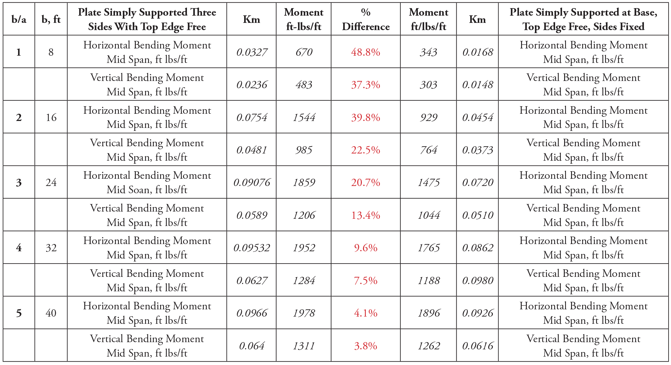
Table 2. Bending moment comparison.
Case Study
Assume an 8-inch concrete foundation wall, 8 feet high by 24 feet long, supported at the top of the wall with 5⁄8-inch anchor bolts spaced at 4 feet on-center, subjected to an equivalent fluid pressure (EFP) equal to 40 pcf.
Treating the wall as simply supported on all four sides from Figure 3, the top edge reaction equals 430 lbs/ft. With the anchor bolts spaced at 4 feet on-center, the shear force per anchor bolt equals 1720 lbs. Referring to the 2018 National Design Specification for Wood Construction, page 99, Table 12E, the allowable shear force is on the order of 400 pounds, less than the applied load.
The solution at this point could consist of decreasing the bolt spacing to approximately 1 foot on-center or designing the wall as a flat plate supported on three sides with the top edge free. In most cases, the contractor will balk at installing anchor bolts at 1 foot on-center which leaves the designer with the option of designing the wall reinforcing by treating it as a flat plate free at the top and supported on the three remaining sides.
To determine the horizontal and vertical steel, one could conservatively assume free at the top and pinned at the remaining three sides. The resulting horizontal and vertical bending moments can be calculated using Figure 4 and are equal to 1.86 and 1.21 ft-kips/ft, respectively. Assuming “vertical edges fixed” results in a reduction of approximately 21% and 13% for the horizontal and vertical bending moments, respectively, based on Figure 5. Horizontal bending moments at the vertical edges can be conservatively determined utilizing Figure 6, resulting in 3.77 ft-kips/ft.
Table 3. Required reinforcing steel (case study).
Table 3 shows the required reinforcing steel.
Table 4 shows a comparison of the reinforcing for an 8- by 24-foot wall simply supported on four sides based on the prescriptive method in the 2012 IRC and the charts developed via the FEM method. Concrete strength is 4 ksi and steel yield is 60 ksi, with reinforcing in the middle of the wall.
Table 4. Reinforcing comparison.
The IRC is based on the premise that the top of the wall provides adequate support such that only beam action is considered spanning from top to bottom. As noted earlier, in some cases an inadequate connection potentially exists at the top of the wall. As a result, one must first determine if the connection at the top of the wall can provide adequate support and then design the wall accordingly. The reinforcing vertical steel for the prescriptive IRC method is based upon treating the wall as a simply supported beam from top to bottom; whereas, the FEM method considers plate action. Safe designs require having justifiable assumptions that adequately account for real-world behavior. The use of these design aids can help the practicing engineer meet code requirements by providing a rational basis for answering the question “what constitutes lateral support at the top of the wall?”■
References
Theory of Plates and Shells, S. Timoshenko and S. Woinowsky-Krieger, McGraw Hill Book Company 1959.
Rectangular Concrete Tanks, Portland Cement Association Document ST 63.
2012 International Residential Code for One- and Two-Family Dwellings, International Code Council.