
Nondestructive Evaluation Methods
Reinforced masonry is used throughout the United States as a cost-effective and desirable building form for commercial, residential, institutional, and industrial construction. Reinforced masonry is a form of composite construction where the masonry units resist compressive stress and internal reinforcement resists tensile stress developing primarily from flexure and shear actions. Vertical and horizontal reinforcement is placed in hollow cells of concrete or clay masonry units (Figure 1), or within internal spaces of multi-wythe masonry wall systems. The reinforced masonry system relies on cementitious grout, encapsulating reinforcement for bond, to transfer stresses as a composite system. Masonry walls may be fully grouted with all internal spaces filled. In many parts of the U.S., it is more common to have partially-grouted construction with grout placed only at reinforced cells.
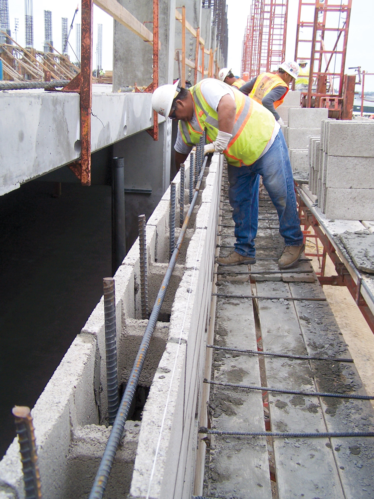
Figure 1. Reinforced concrete masonry construction.
Nondestructive evaluation (NDE) methods are based on the concept of interpreting how different forms of energy interact with the material being evaluated. NDE techniques use energy from many parts of the electromagnetic spectrum to evaluate masonry materials, including visible light, x-ray radiation, infrared emissions, and microwaves. Stress wave energy is also used for some nondestructive methods, introduced into masonry as a mechanical hammer tap or an energy pulse from an ultrasonic transducer. Energy is reflected, absorbed, or otherwise altered as it passes into, through, or out of a masonry wall, and interpreting the material’s effect on that energy gives an indication of masonry properties, geometry, and condition.
Reinforced masonry construction is evaluated for several reasons.
- Determining construction geometry, wall thickness, and thickness of individual wythes
- Locating internal metals including horizontal and vertical reinforcement, anchors, pipes, and conduit
- Identifying solid-grouted areas and voids
- Determining grouted areas for locating post-installed anchors
- Evaluating distress such as cracks or spalls
Evaluation information is used for structural analysis, to guide repairs, and to help understand the causes of distress.
Diagnostic Methods
In its simplest form, existing construction can be evaluated by opening destructive probes to visually examine internal conditions. Fiber optic borescopes and videoscopes, inserted into small-diameter holes drilled into mortar joints, provide a less destructive approach for visually observing internal wall conditions.
Nondestructive methods are attractive because they do not disfigure or otherwise harm masonry construction. Methods range from localized measurements to global techniques. Some approaches are non-contact, but most require close-up access to the wall surface for rolling antennae or coupling small transducers to the masonry.
Sounding
Sounding methods introduce sonic stress waves by tapping with a hammer and listening to the sound generated (Figure 2). The method is effective for locating near-surface spalls and hollow areas and, if the correct sounding hammer is used, grouted masonry cells. Sounding over voids gives off a dull, low-frequency sound, whereas a higher-pitched ringing is heard at solid areas. Different sized hammers are used depending on the substrate hardness and density, and the depth of the expected void space. For concrete masonry construction, a mason’s hammer, ball-peen hammer, or ball bearing welded to a metal rod work well for locating grouted and hollow cells (Figure 2).
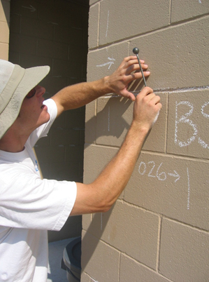
Figure 2. Sounding hammer used to locate hollow and grouted cells in concrete masonry construction.
X-Ray Imaging
For decades, x-ray imaging was the nondestructive method of choice for evaluating internal conditions of masonry and other construction. Two-dimensional x-ray images provide a snapshot of internal conditions, showing reinforcement, unit cross webs, grout, and internal voids. High-power x-ray sources required to penetrate massive masonry wall sections are hazardous to humans, and the method has mostly fallen out of favor in recent years for other, safer, methods.
Ultrasonic Pulse Velocity
The speed at which high-frequency ultrasonic stress waves travel through walls provides a direct indication of material density and dynamic modulus, and may be correlated with compressive strength. Waves travelling around internal voids and cracks give an apparent change to straight-line velocity, thereby indicating internal anomalies (Figure 3). The approach for locating internal voids or solid-grouted cells involves placing ultrasonic transmitters and receivers on opposite wall faces, coupled to the wall with low impedance gel or rubber pads. Greater measured velocities indicate solid, high-density material, whereas low velocities are recorded at areas with internal voids, cracks, or delaminations. Pulse velocity techniques provide a local measure and require access to both wall faces to acquire a series of point-by-point velocity measurements.
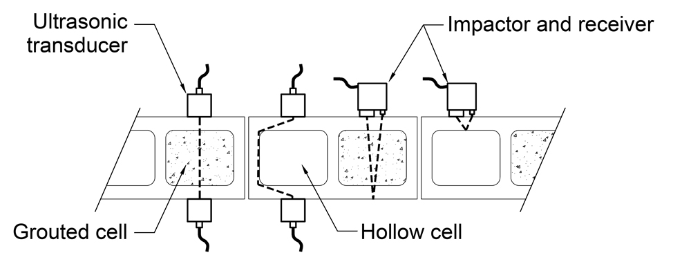
Figure 3. Ultrasonic waves travel through grouted cells and around hollow cells, altering the apparent wave velocity (left). With the impact-echo method (right) waves reflect off the back wall face at solid-grouted areas and reflect off the face shell at empty cells.
Ultrasonic Imaging
Imaging systems developed for use with concrete construction are also used to identify solid grouted construction (Figure 4), internal cracks, voids, spalls, and delaminations in masonry construction. The method uses an ultrasonic array system with an external processor to develop a 2-dimensional representation of internal conditions based on arrival times of reflected pulses. The system is automated and provides for assessment, in a matter of seconds, of areas approximately 4 inches by 8 inches.
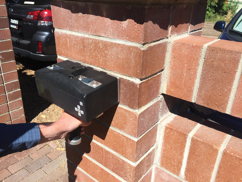
Figure 4. Ultrasonic imaging equipment used here to determine solidity of a reinforced clay masonry column.
Impact-Echo
Low-frequency stress waves, generated with an impactor, travel into masonry and are reflected at internal discontinuities (Figure 3).
Knowing the characteristic stress wave velocity, the depth to a discontinuity is calculated based on the time and frequency of reflected waveforms. The method is useful for locating voids in grouted masonry construction and member thickness. Originally developed for use with concrete construction, equipment can be used for masonry evaluation, but the interpretation is complicated by stress wave reflections off nearby mortar joints.
Pachometer
A pachometer, sometimes called a cover meter or metal detector, generates an electromagnetic field with a hand-held search head (Figure 5). Ferrous and non-ferrous conductive materials in the vicinity interact with the electromagnetic field to indicate the location, depth, and size of the embedded metal. These devices are most commonly used to locate reinforcement in concrete construction and are also used to locate structural reinforcement, joint reinforcement, and veneer anchors in masonry walls. Equipment sensitivity is optimized for use with concrete, and most devices have a maximum detection depth of 4 to 6 inches for common reinforcement sizes.
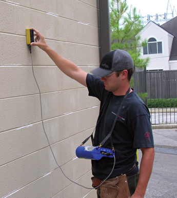
Figure 5. Locating vertical and horizontal masonry reinforcement with a pachometer.
Surface Penetrating Radar
More commonly known as “ground penetrating radar” for its use with archeological investigations, surface penetrating radar used for masonry NDE uses an antenna mounted in a small, hand-held cart that is rolled over the wall surface (Figure 6). Electromagnetic waves in the microwave frequency range are generated thousands of times each second; these waves propagate into the wall and are reflected at interfaces between materials with varying electrical properties. Waveforms are displayed on the processor screen for analysis and interpretation. The method is highly sensitive to internal metals and voids and is commonly used to map reinforcement, wall thickness, grouted cells, void spaces, and separations within masonry walls. Lower frequency antennae provide greater penetration depth to locate reinforcement at 16 inches or greater; high-frequency antennae provide better resolution of internal conditions. Microwave energy is absorbed (attenuated) by internal moisture and salts, limiting the usefulness of the method in these conditions.
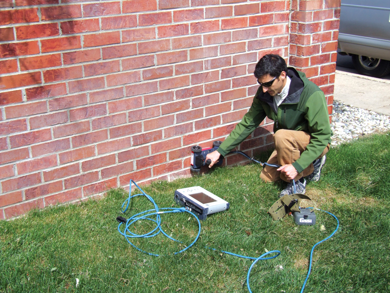
Figure 6. Surface-penetrating radar equipment in use to locate reinforcement and grout in clay masonry construction.
Infrared Thermography
Infrared images are acquired by special cameras that measure heat energy emitted from wall surfaces in the infrared range. The method is a non-contact, global approach permitting rapid evaluation of large regions. In a state of heat flux, differences in surface temperature represent materials with different emittance values, density, heat capacity, and/or thermal conductivities. Thus, wall surface temperature is affected by internal voids, spalls and cracks, and varying material density. Heat energy must be traveling into or out of wall surfaces for successful imaging. Good images are generated when internal building temperature is regulated to provide a minimum temperature differential of 20 to 30ºF across the wall section. Alternatively, active heating using solar radiation or a bank of infrared lights is used to provide a state of heat flux. The infrared image in Figure 7 was taken after 3 hours of direct sunlight. Hollow areas heat rapidly and show as high-temperature zones; grouted cells have greater thermal mass and show as cooler areas. Infrared images are also used to detect wall moisture; damp walls transmit heat energy at a greater rate than dry walls, and moisture evaporation at the wall face tends to have a localized cooling effect.
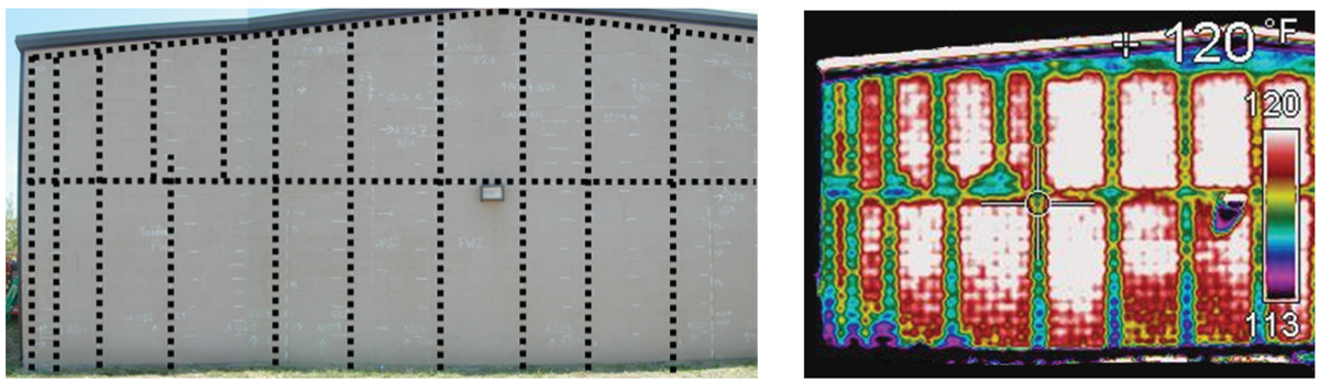
Figure 7. Concrete masonry construction: reinforcement located with pachometer scanning is shown as dashed lines in the left image; infrared image (right) shows internal grouted cells as cooler zones.
Verification and Validation
Interpreting NDE data requires experience and professional judgment, and some level of verification and proof testing is necessary to validate results. Multiple techniques are often used in the same area as a form of verification, and conditions requiring expensive repairs should always be confirmed. For example, voids detected using radar scans could be verified using ultrasonic or infrared imaging and evaluated visually using a videoscope inserted into the void space.■