
New London, Connecticut, 1889
Alfred P. Boller (STRUCTURE, November 2011) had already designed swing bridges across the Pequannock River, Harlem River, Hudson River, Ft. Point Channel, and the Arthurkill when he was called to be the designer of the longest swing bridge in the United States across the Thames River in Connecticut.
Preliminary surveys of the site to replace a train ferry started in 1859 for the Stonington Railroad, but the Connecticut legislature did not pass an act approving the New York, Providence, and Boston Railroad to build the bridge until January 1882. A commission of Army Engineers was appointed that approved of the site at the narrowest point along the river. Boller was authorized to proceed with his first design in the summer of 1882 for the bridge between New London and Groton, Connecticut, across the Thames River. It utilized Whipple double intersection trusses and had a swing span of 500 feet with two 310-foot approach through-spans and two 150-foot deck-spans on each shore. His design was placed before an independent panel of engineers that issued a favorable report on March 28, 1883. The plans were submitted to a select panel of engineers consisting of C. C. Martin, Octave Chanute, and Col. J. Albert of the Corps of Engineers. Congress passed an act in May 1883 approving the bridge, with the proviso that another panel of military engineers approve of the final plans. Congress approved the bridge and designated the road as a Post Road.
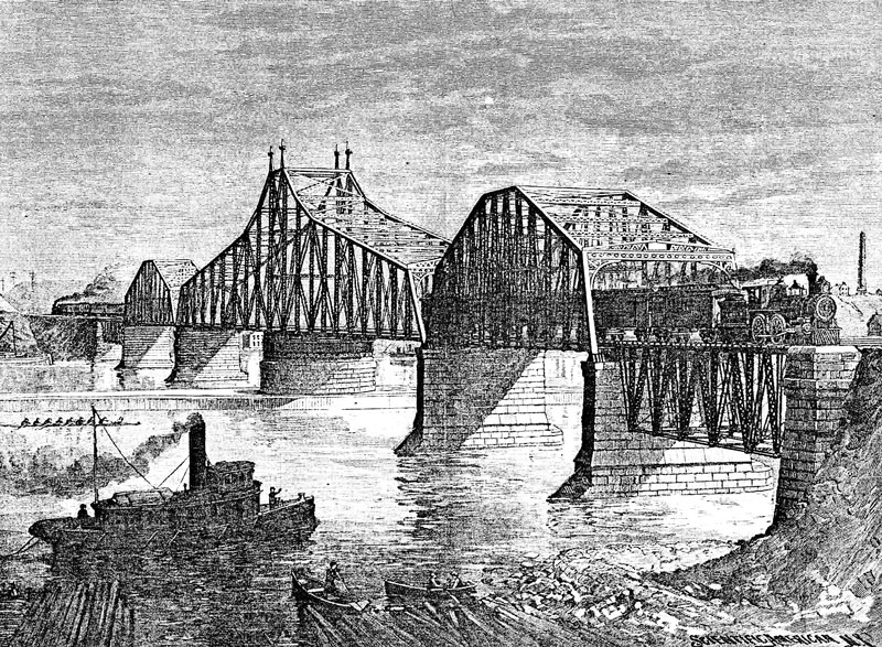
Artist’s Conception, Scientific American, June 8, 1889.
The long, two-track swing span was later fixed in the spring of 1884 by a panel consisting of three Army Engineers and two Navy Engineers to ensure there was adequate clearance for ships using the United States Naval Station just upstream. The clear passage on each side of the swing pier was 225 feet, and the vertical clearance on the three central spans was 32 feet. The weight of the swing span was 1,000 tons. They approved of the location on July 25, 1884, but raised the spans six feet and called for pointed icebreakers on the upstream faces of the piers. The railroad approaches were approved by the cities of Groton and New London on May 15, 1884. The railroads then got into a debate as to whether the bridge should be single-tracked or double-tracked and ordered Boller to prepare an estimate for both possibilities. He found that, with improved designs and lower prices then prevalent, he could build a double-track bridge for his original estimate for a single-track bridge. It was not until 1888, four years later, that all the financing was approved by the two railroads and bids received. On April 6, 1888, the construction contract was awarded to the Union Bridge Company run by Charles Macdonald and others. The bridge as built differed from the initial design with single intersection trusses and two fixed spans of 150 feet, two fixed spans of 310 feet, and a swing span 503 feet long with four panels adjacent to the swing towers of the top chord on a parabolic curve.
The first design of the Thames River Bridge, early 1880s, with 500-foot swing span.
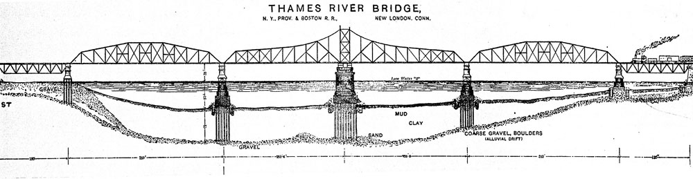
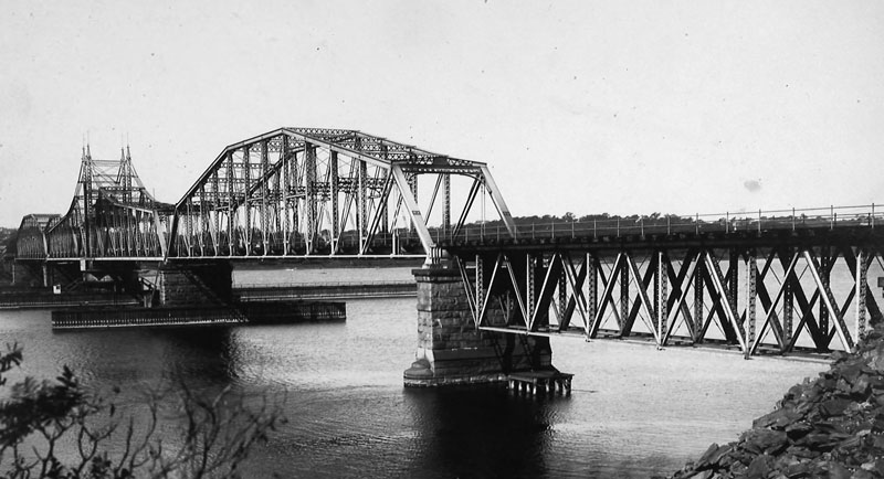
The second design of the Thames River Bridge, 1888, with a 503-foot swing span.
Foundation problems were compounded by the fact that the river was 40 to 60 feet deep and bedrock was at a depth of 130 feet, making pneumatic caissons questionable. Boller arrived at the following construction procedure.
- Wooden cribs, built with two walls of 12 x 12 inches with a space of 8 feet apart and cross-braced, were sunk and the mud dredged out with the cribs sunk to a bottom of 70 feet below the water level. The 8-foot space was filled with rock to help in the advancement of the cribs and extensions added on top to keep the top of the crib above the water level.
- The cribs were supported by interior cross walls that also left pockets in which to drive the piling.
- Wood piles 85 to 95 feet long were then driven to bedrock in the pockets.
- The piles were cut off at the new mud line and sand in deep water.
- The tops of the piles were encased in tremied concrete.
- Caissons were then floated into place and sunk until they set on the concrete, and then pumped out.
- The masonry was placed in the dry in these caissons.
After the swing pier was completed, up to three courses from the top, a test load of 2,672 tons of iron ingots was placed to ensure its load carrying capacity. A maximum settlement of 5 inches was observed. At the same time, it was discovered that the stonework was not coming up level requiring the last three courses to be cut to ensure the top of the pier was level, necessary to make the swing table work properly. Boller’s colleague, Alexander McGraw, placed the foundations and masonry. Construction on the foundations started in June 1888. The entire project was completed in 16 months, with its grand opening on October 10, 1889. It carried two tracks and, in profile, resembled Boller’s Eighth Avenue span across the Harlem River. Mr. Babcok, President of the Railroad at the dedication, commended Boller, stating, “The bridge will stand as a monument to your labor and skill. Although the Company furnished the money, neither the Directors nor the stockholders had the brains to do the great work. It is indeed a work the Company has every reason to be proud of.” The total cost of the project, including the approach trackage, was $1,600,000.
The Railroad and Engineering Journal wrote of the bridge,
The aesthetic features of the structure have evidently been studied, as well as its purely engineering features. It is gratifying to know that the design is not only graceful and pleasing, but that it is also economical. The excuse for making structures hideous and unsightly is that it would be too expensive to make them otherwise. As a matter of fact, the ugliness of bridges is due generally to the absence of a sense of beauty or grace in their designers. In the present instance, the Engineer of the Thames River Bridge was an artist as well and, as a result, both the engineering and the artistic effects are good and neither was sacrificed for the other, and, in fact, the science of the engineer seemed to improve the work of the artist, and vice versa.
Boller wrote a lengthy report on the bridge entitled New York, Providence, and Boston Railroad-Report to the General Manager upon the Completion of the Thames River Bridge and Approaches at New London, Conn. It had 43 pages of text and many drawings and test results. Engineering News wrote of the report,
The total length of new work required by the bridge was 5.13 miles. The chief difficulty in location and construction lay in the piers and abutments and their foundations, the adopted plan calling for a draw-span of 503 feet flanked on either side by spans of 310 feet and 150 feet each. Careful soundings made at the site of the main foundations only reached rock and boulders at depths of 130, 100, and 120 feet below mean low water, and the material overlying this rock was from 60 to 75 feet deep. Pneumatic foundations were out of the question and the ingenious methods adopted and carried out by Mr. BOLLER are fully described and illustrated in this report with an engineering minuteness that makes them of great professional value. The superstructure, with its great swing draw-span of 503 feet, is treated in a similarly careful manner, and is made plain in all its details of design and erection by concise description and complete drawings, with dimensions and sections. As we have before mentioned in this journal, the bridge is not only one of the latest and best examples of American steel bridge design, but its treatment is artistic in general form and detail, and the result proves conclusively that even so utilitarian an object as a railway bridge can be made a pleasing object to the eye without practical increase in cost. The bridge proper only cost $658,489, though the entire cost of land, approaches and general account swelled the final cost to $1,293,939. In appendices are given the official tests of the bridge, the full specifications of foundations and superstructure, the weight of metal in the truss spans, full-sized eye-bar tests, and the various other finished material tests. The illustrations are from photographs taken during and after erection, and the various detail sheets of foundations and superstructure are facsimiles of Mr. BOLLER’s own plans, these latter including the turntable and gearing and end-locking gear. Taken altogether, it is a model report and proves how useful a complete record of a difficult and important piece of work can be made to the engineering profession when the engineer in charge goes conscientiously to work. The final regret is that reports of this kind are too rarely issued by the executive officer, who is alone able to fully detail the true history, and that it is still more rare to find corporations willing to publish such reports when made.
Thames River Bridge.
It remained the longest swing span in the country until 1893 when the Omaha Bridge and Terminal Railroad built a bridge, by J. A. L. Waddell, across the Missouri River at East Omaha, Nebraska, with a span of 520 feet. Despite all of Boller’s efforts, the easterly pier of the Thames River Bridge started to settle and shift to the south. In 1908, rail traffic was limited to one track and, in 1919, when a new railroad bridge was built, it was converted into a vehicular bridge carrying U.S. Route 1 across the river. It was replaced in 1943 with a high-level bridge, the Gold Star Bridge, that is now part of I-95.■