
Composite steel deck-slabs, referred to hereafter as composite slabs, have been successfully used without supplemental reinforcing in buildings with relatively short spans and typical design loads. As slab spans become longer or slab design loads become heavier, adding reinforcing bars is an effective alternative to making the composite slabs deeper and the steel decks thicker. Properly designed supplemental reinforcing allows for light, slender composite slabs that can span longer distances and results in large open interior spaces. This is in addition to the benefits of conventional composite slabs, such as reductions in construction time and cost. This article discusses different strategies for achieving economical composite slab designs by adding steel reinforcement and gives practical guidelines for the design of composite slabs with supplemental reinforcing bars.
Typical Designs
Designers usually specify composite slabs based on composite steel deck load tables developed and published by deck manufacturers. The load tables are generally applicable to simple-span slabs; although, load tables for continuous slabs with supplemental top bars over interior slab supports are available. Allowable loads published in these load tables have been determined based on comparisons of slab capacities for different limit states with slab internal forces. The American National Standards Institute/Steel Deck Institute C-2017, Standard for Composite Steel Floor Deck-Slabs (ANSI/SDI C-2017), gives provisions for calculating slab capacities. The internal forces are determined from structural analysis of a composite slab as a beam. For simply supported slabs and uniform loads, the structural analysis consists of using well-known expressions for maximum shear, moment, and deflection in a simply supported beam. Slab deflections are calculated using the average of cracked and uncracked moments of inertia of the transformed section and are compared to required deflection limits.
To achieve a longer span or greater allowable loads for a simply supported composite slab without reinforcement, the designer should specify a deeper slab, a heavier deck, or greater strengths of the materials. Adding properly designed reinforcing bars may be a more appealing option, which results in a shallower composite slab formed on a lighter steel deck.
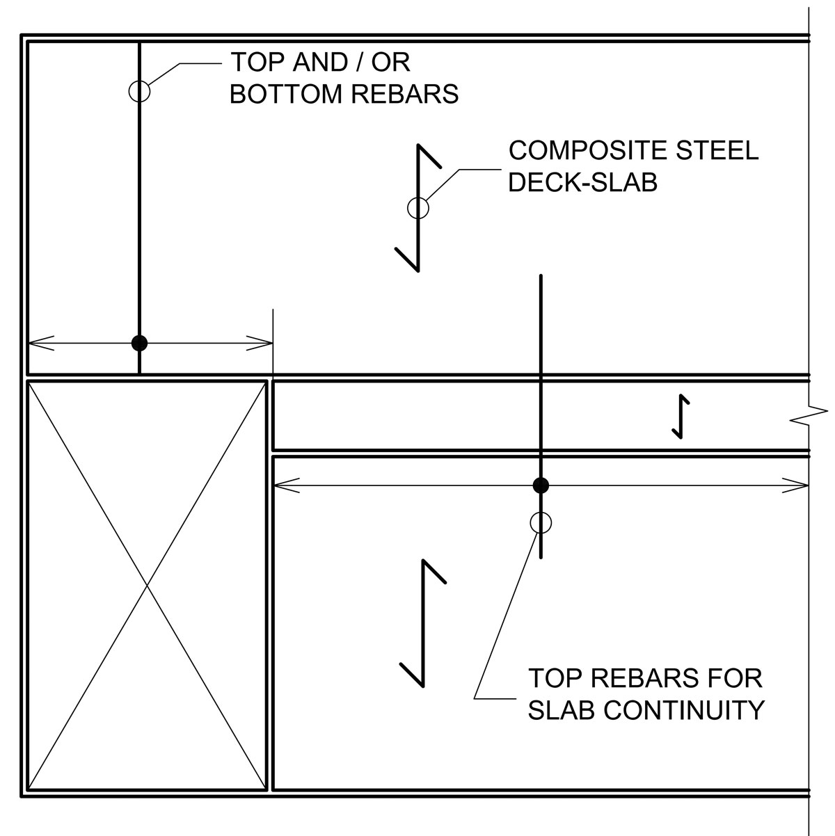
Figure 1. Floor plan with composite slab and supplemental reinforcing bars.
Reinforcing bars can be added in three different locations. Top bars above interior supports provide composite slab continuity. Bottom bars between composite slab supports contribute to improved positive moment capacity and allow for establishing fire resistance of the slabs. Top bars between composite slab supports help to control long-term deflections of the slabs. Figure 1 shows an example of a floor plan with a composite slab including supplemental reinforcing bars. Figure 2 illustrates the typical locations of the top and bottom bars within the composite slab cross-section.
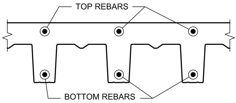
Figure 2. Typical locations of reinforcing bars in slab cross-section.
Top Bars for Slab Continuity
Properly designed top reinforcing bars installed above interior supports make the composite slab continuous. A composite slab without such bars is considered simply supported even when the steel deck is continuous over several spans. When gravity loads are applied to a composite slab without top continuity bars, cracks form in the concrete above the interior supports, which causes the slab to behave as a series of simply supported slabs. The maximum positive bending moment and maximum deflection of a continuous slab due to applied loads are considerably smaller than those in a simply supported slab with the same spans and loads, which allows for longer continuous spans when compared with simply supported slabs of the same depth (Figure 3).
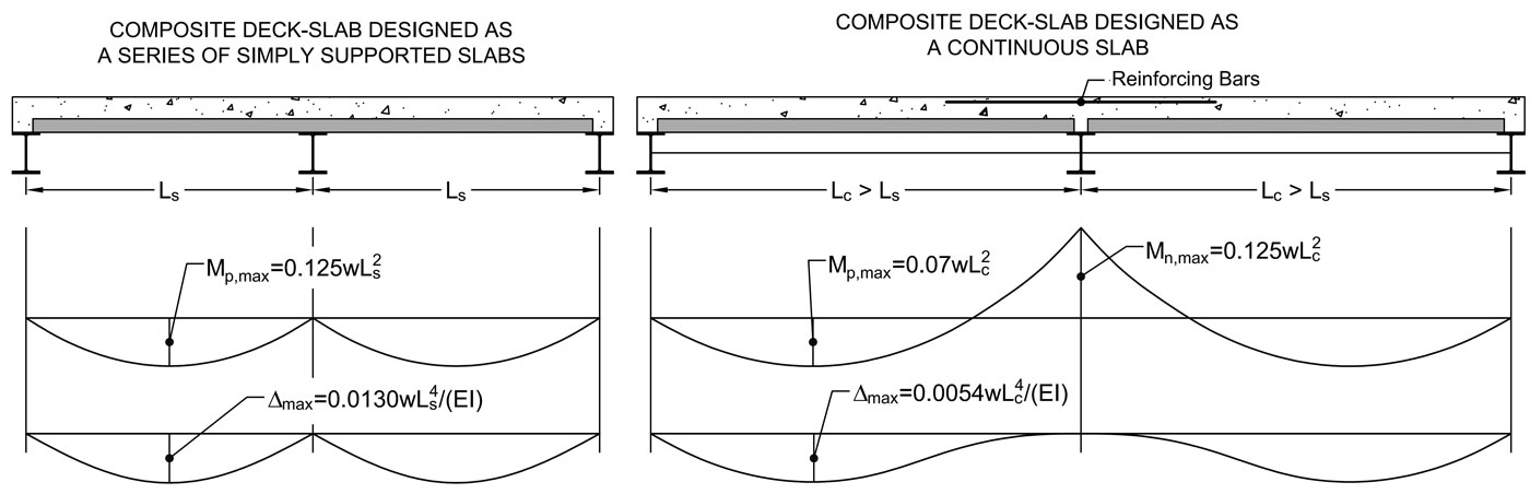
Figure 3. Simply-supported and continuous composite slabs.
Design of Continuous Slabs
For the analysis, the composite slab is divided into strips based on the support layout and loading conditions. For example, the single-span composite slab area adjacent to the opening in Figure 1 would be one strip, and the remaining composite slab area, with three unequal spans, would be another strip. Because composite slabs are designed as one-way slabs, every strip is analyzed as a beam accounting for load combinations required by the building code.
For simple cases of approximately equal spans, applied moments and shears can be determined using moment and shear coefficients tabulated in the American Concrete Institute’s (ACI) Building Code Requirements for Structural Concrete (ACI 318-14) and Commentary (ACI 318R-14), similar to the process for simply supported slabs. Composite slab deflections can be calculated using deflection coefficients for continuous beams with equal spans available in the technical literature. When spans are unequal, the composite slab should be analyzed using a general purpose structural analysis software considering pattern loading and load combinations required by the building code. Figure 4 shows an example of such analysis and resultant moment, shear, and deflection diagrams.
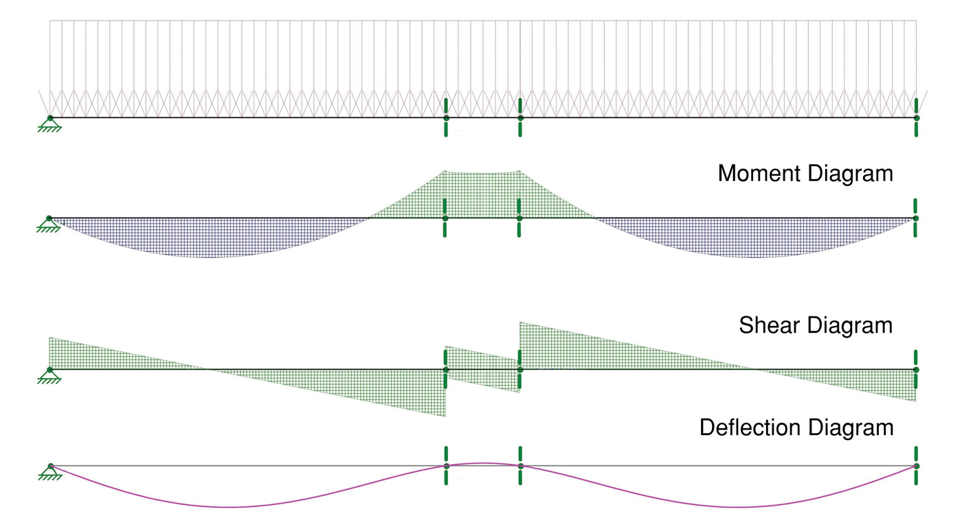
Figure 4. An example of analysis results for a continuous slab with unequal spans.
The calculated composite slab internal forces are compared with composite slab capacities calculated in accordance with ANSI/SDI C-2017. The composite slab’s flexural resistance in positive bending, vertical shear capacity, and the average moment of inertia can be obtained from the deck manufacturer or can be back-calculated from composite slab allowable loads published in manufacturers’ deck load tables. The negative moment capacity of a composite slab is determined in accordance with ACI 318-14, neglecting the steel deck contribution, as follows:
ΦMn = ΦfyAtr(dtr – 0.5a)
where
a = (fyAtr)/(0.85f´cbb) and all other variables are as defined in ACI 318-14 and in Figure 5.
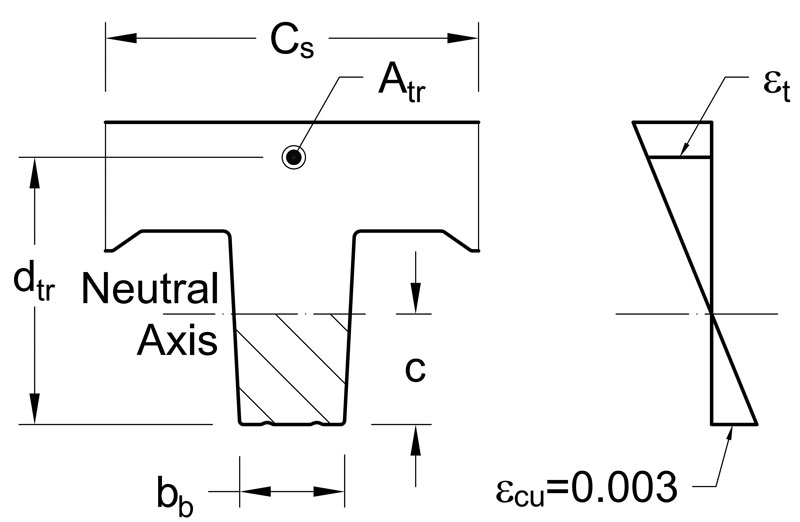
Figure 5. Composite slab design diagrams for negative bending moment calculations.
The negative moment reinforcing detailing – including the concrete cover, reinforcement spacing, and minimum reinforcement area – are determined in accordance with ACI 318-14. The tensile strain in the negative moment reinforcing bars, εt = [(dtr – c)/c]εcu,
is required to be at least 0.004 by ACI 318-14 to prevent brittle failures. This requirement may prohibit the use of large amounts of reinforcement in composite slabs with relatively narrow ribs, which will limit the maximum negative moment capacity that the slab can achieve. If that is the case, the tensile strain in the top bars can be increased by providing bottom (compression) reinforcement in the slab ribs in the negative bending moment region. The larger tensile strain will allow for a greater amount of the top reinforcement and a greater negative moment capacity of the slab.
Additional Bottom Bars for Moment Capacity
Bottom reinforcement may be provided in composite slab ribs between supports to improve the positive moment capacity of the composite slab. A greater positive moment capacity may be required to attain longer spans or to accommodate heavier design loads. Adding bottom reinforcement for the higher moment capacity is an alternative to using a heavier-gauge steel deck. This option may be justified where a heavier-gauge steel deck is not available or where the greater moment capacity is required for a relatively small slab area, such as the slab area adjacent to the opening in Figure 1. Instead of introducing a different gage for the steel deck over a small floor area, bottom reinforcing bars can be added to the composite slab to achieve the required moment capacity. However, a heavier-gage steel deck (if available) is generally a better option when a greater moment capacity is required over a large area of the floor. In those cases, the heavier-gauge steel deck will eliminate expenses associated with the additional reinforcement installation and will produce longer unshored spans, which may reduce or eliminate the required deck shoring.
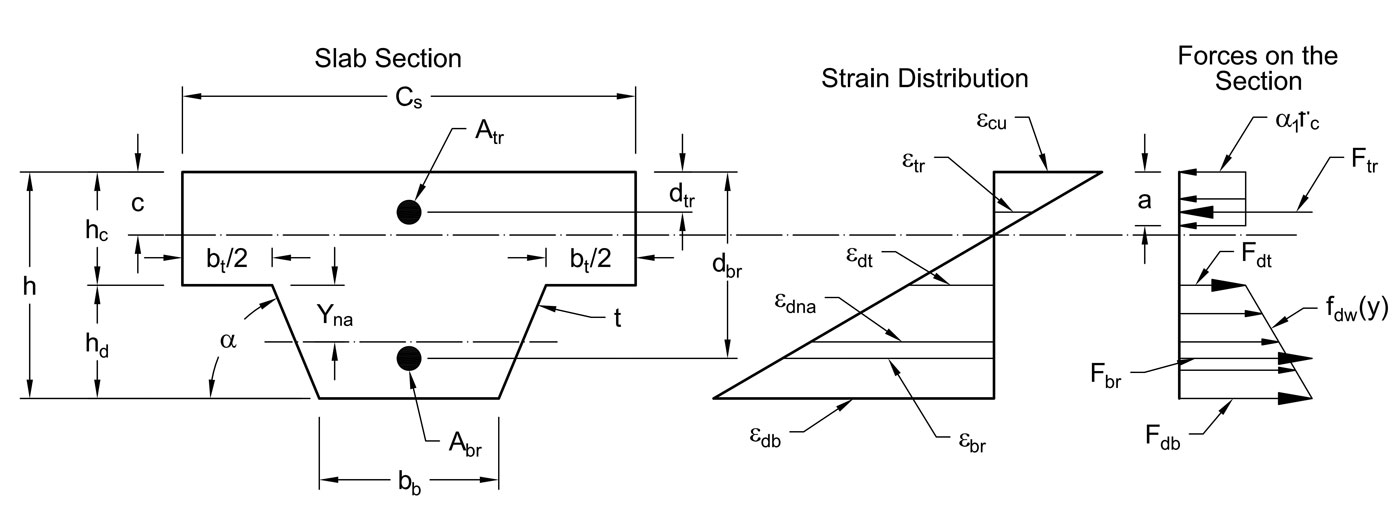
Figure 6. Design diagrams for the GSA method.
The positive moment capacity of a composite slab with supplemental reinforcement can be determined using a general strain analysis (GSA) method outlined in the American National Standards Institute/American Society of Civil Engineers’ Standard for the Structural Design of Composite Slabs (ANSI/ASCE 3-91). The GSA method is based on the considerations of the composite slab internal-forces equilibrium and strain compatibility, as well as on the constitutive material models for the steel and concrete. Figure 6 illustrates the method. The following equilibrium equations of the internal forces and moments can be written for the composite slab cross section:
Fc + Fdt + Fdw + Fdb + Ftr + Fbr = 0
Fcxc + Fdtxdt + Fdwxdw + Fdbxdb + Ftrxtr + Fbrxbr = Mn
where
Fc, Fdt, Fdw, Fdb, Ftr, and Fbr are internal resultant forces in concrete, steel deck top flange, steel deck web, steel deck bottom flange, top reinforcement, and bottom reinforcement, respectively (positive when in tension and negative when in compression);
xc, xdt, xdw, xdb, xtr, and xbr are distances from the neutral axis of the composite section to the internal resultant forces in concrete, steel deck top flange, steel deck web, steel deck bottom flange, top reinforcement, and bottom reinforcement, respectively (positive when resultant force is below neutral axis and negative when resultant force is above neutral axis); and Mn is nominal moment capacity of composite section.
The internal forces in the concrete, steel deck and reinforcement are expressed in terms of the internal stresses in the slab components and the areas of the components to which the stresses are applied. Afterward, the stresses in the components are expressed based on the assumed stress-strain relationships for the materials, as functions of strains. The strains in the slab components are related based on the hypothesis of plane sections shown in Figure 6.
The resulting equations of the GSA method are quite cumbersome and generally require a computer to solve. Some deck manufacturers can provide positive moment capacities of composite slabs with supplemental reinforcement calculated using this method.
It should be noted that either the ultimate flexural strength of the composite slab section or the bond between the steel deck and the concrete may govern the flexural resistance of a composite slab in positive bending. The GSA method, which is based on the assumption of the perfect steel deck-to-concrete bond, allows for determining the ultimate flexural strength. The composite slab flexural capacity governed by the bond should also be checked. The bond-governed strengths of composite slabs are steel-deck-profile specific and can be provided by the deck manufacturer.
Additional Bottom Bars for Fire Resistance
Bottom reinforcing bars can also be added between slab supports to establish fire resistance of the composite slab by rational design in accordance with the building code. This approach may be justified when an Underwriters Laboratory (UL)-approved slab design assembly is not available or when the rational design results in a more economical solution when compared with the available UL designs. The 2015 International Building Code (IBC) permits establishing fire resistance of concrete slabs by calculations in accordance with ACI/The Masonry Society Code Requirements for Determining Fire Resistance of Concrete and Masonry Construction Assemblies (ACI/TMS 216.1-14). To apply ACI/TMS 216.1-14 to composite slabs, the steel deck is neglected in the design for a fire event and the slab is analyzed as a reinforced concrete slab. Because the steel deck is neglected, the required moment capacity of the concrete slab in positive bending is achieved by adding bottom reinforcement.
In a fire, heat transmission and structural end-point behaviors govern slab design. Based on heat transmission end-point behavior, the concrete slab must meet the minimum required equivalent thickness specified in the building code. The minimum required concrete slab thickness is a function of the required fire-resistance rating and concrete type. Thicker concrete slabs and lesser concrete densities provide higher fire-resistance ratings. The building code gives guidelines for calculating the equivalent thickness of a concrete slab with ribbed soffit, which is a function of the slab’s cross-sectional shape and dimensions.
Based on structural end-point behavior, the reduced capacity of the reinforced concrete slab is determined using multiple charts given in ACI/TMS 216.1-14 for different concrete types and durations of fire exposure, which correspond to fire-resistance ratings. First, temperatures of concrete and bottom reinforcement are determined. The reinforcement temperature depends on the concrete rib width and the distance from the reinforcement to the bottom of the slab. Once the reinforcement and concrete temperatures have been established, the reduced strengths of the materials are determined using ACI/TMS 216.1-14 charts, which show percentages of the retained material strengths as functions of the material temperatures. Finally, the slab’s nominal moment capacity is calculated using the reduced strengths of the reinforcement and concrete and compared with the unfactored full-service load moment in the concrete slab. The bottom reinforcement amount is adjusted as needed for the concrete slab to achieve the required moment capacity after the required period of fire exposure.
Long-Term Deflection Control
According to ANSI/SDI C-2017, additional composite slab deflection due to concrete shrinkage and creep shall be taken into consideration. The 2015 IBC also requires the long-term deflection of floors due to concrete shrinkage and creep be considered in the composite slab design. Deflection requirements rarely govern the design of conventional composite slabs with relatively short spans and typical design loads. For slender, long-span composite slabs, deflection control is a primary design consideration that often governs composite slab design. Research on the long-term behavior of composite slabs is limited, but the available experimental studies clearly show that deflections of composite slabs increase over time under constant loads due to concrete shrinkage and creep, similarly to deflections of reinforced concrete members.
Due to the limited research on composite slabs, ACI 318’s long-term deflection provisions have been considered applicable to composite slabs. The long-term deflection of a composite slab is determined by multiplying the calculated instantaneous slab deflection due to sustained loads by the long-term deflection factor, ∆LTD = λΔi,sust. The long-term deflection factor is a function of the sustained load duration and the amount of reinforcement in the concrete compression zone. Experimental studies on reinforced concrete flexural members showed the beneficial effect of compression reinforcement on the reduction of long-term deflections. For a load duration of 5 years and more, the composite slab long-term deflection factor can be calculated using either the ANSI/ASCE 3-91 equation
λ = [2-1.2(A’s/A”s] ≥ 0.6
or the ACI 318-14 equation
λ = 2/(1+50ρ´)
where
A´s and A”s are areas of steel in compression and tension, respectively;
ρ´ is the ratio of compression reinforcement.
Therefore, top reinforcing bars between supports reduce composite slab long-term deflections and may be a cost-effective alternative of using a deeper section in the cases where deflections govern composite slab design. Top reinforcing bars have a small effect on the composite slab positive moment capacity and can be conservatively neglected in positive moment capacity calculations. If desired, the described GSA method can be used to account for the effect of the top bars on the composite slab positive moment capacity.■