
The recently completed SR 99 Tunnel was constructed as part of the Washington State Department of Transportation’s (WSDOT) Alaskan Way Viaduct Replacement Program. The existing Alaskan Way Viaduct (AWV) is an aging double-deck highway structure in Seattle, Washington, that was built in the 1950s. The Viaduct has been deteriorating due to age as well as damage resulting from the 2001 Nisqually earthquake. The SR 99 Tunnel consists of three segments: the South Approach, the Bored Tunnel, and the North Approach. The South and North Approaches include cut-and-cover tunnels and U-sections.
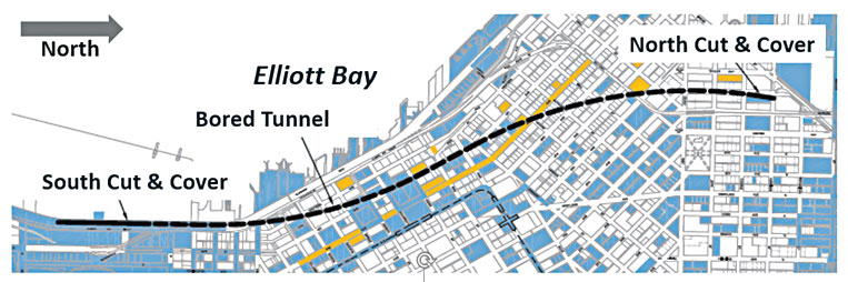
Figure 1. SR 99 Bored Tunnel and Approaches.
The bored tunnel begins south of downtown Seattle in close proximity to the seawall of Elliott Bay, tends north along the existing Alaskan Way Viaduct, then crosses under the Viaduct, traverses under downtown Seattle, and emerges north of downtown Seattle just east of the Space Needle (Figure 1). The bored tunnel is 9,300 feet long with an outer diameter of 56 feet and was excavated by an Earth Pressure Balance (EPB) Tunnel Boring Machine (TBM), named Bertha, with a 57½-foot-diameter cutterhead. The bored tunnel was the largest in diameter in the world at the time of design (Figure 2). At its lowest point, the tunnel crown is at elevation -95 feet, and it is 215 feet deep at its greatest depth below grade. Development along the alignment consists of on-grade and elevated roadways, buildings ranging from single-story to high-rise structures, railroad and sewer tunnels, and public and private utilities.
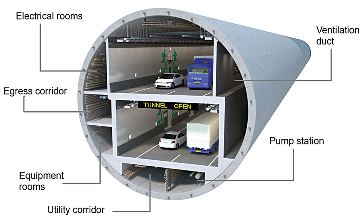
Figure 2. SR 99 Bored Tunnel configuration.
In December 2010, WSDOT awarded the SR 99 Bored Tunnel Design-Build Project to Seattle Tunnel Partners (STP) based on best technical solution and cost. STP is a joint venture between Dragados USA and Tutor Perini Corp. The design team includes HNTB Corporation, Intecsa of Spain, Hart Crowser, Inc., and EMI Inc. HNTB was responsible for the design of the lining and approach structures. After close to two years of design and preparations, TBM Bertha was launched and began drilling in July 2013. Only five months later, Bertha halted drilling due to overheating of some of her components. After two years of repair and preparation, Bertha resumed mining in February 2016 and finally broke through into the receiving pit in April 2017. Although the TBM work was put on hold during Bertha’s repair, construction of the approaches and some interior structures continued during that time.
Geology
Seattle is located adjacent to Puget Sound in the Puget Lowland between the Olympic Mountains to the west and the Cascade Range to the east. The Puget Lowland has been subject to several glacial advances, resulting in a complex stratigraphy of glacial and non-glacial soil deposits. Along its alignment, the tunnel traverses through variable glacially over-consolidated soil deposits with high groundwater pressures of up to 5.2 bars (Figure 3). These deposits are often highly variable within relatively short distances due to the inconsistency in erosion and deposition during the multiple glacial events and interglacial periods.
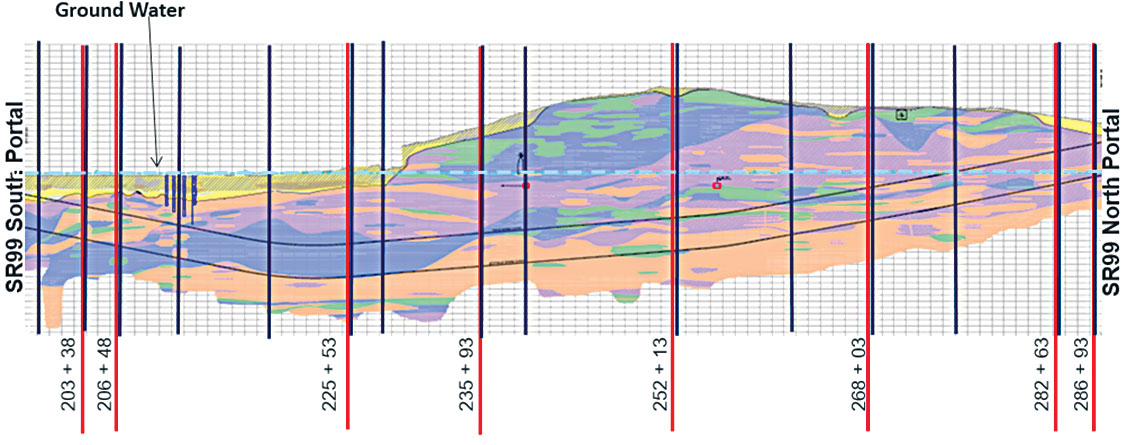
Figure 3. Geotechnical profile and design section locations.
Design
Design geologic sections were selected to assess the geologic variability along the tunnel alignment, as well as topographic/geometric variability and building structure locations. As shown in Figure 3, 15 geologic sections (shown in blue) were selected for static design and 8 sections (shown in red) for seismic design. For consideration of potential future development, the contract required an evaluation of a 7,000 psf building surcharge applied at the height and width limits of WSDOT’s right of way above the tunnel, which are 54 feet above the crown and 84 feet wide. Existing building and structure foundations vary from spread footings and mat foundations to deep shafts and piles, ranging from 8 to 63 feet long and as close as 16 feet above the tunnel crown. Buildings along the tunnel alignment range from 13 to 546 feet tall with basement excavations ranging from approximately 0 to 87 feet deep.
Dual levels of design earthquakes were considered for the design of the tunnel liner. The Expected Earthquake has a 108-year return period and is associated with Operational Performance Objectives, while the Rare Earthquake has a 2,500-year return period and is associated with Life Safety Performance Objectives. Under the Expected Earthquake, minimal damage to the liner segments, joints, and water tightness is anticipated because the lining is designed to respond in an elastic manner. Concrete compression strain is limited to 0.003, and tensile strain in reinforcing steel is limited to 0.002. Under the Rare Earthquake, the objective is to prevent the collapse of the tunnel liner. Inelastic deformations are allowed under the Rare Earthquake but are limited to the acceptable levels; concrete strain is allowed to exceed 0.003 but limited to 0.005 provided that the strain is predominantly due to flexure. The tensile strains in a mild reinforcing steel are limited to 0.06 for reinforcing bars up to US #10 size and 0.045 for US #11 size and larger.
The tunnel liner was analyzed and designed for two conditions. The first condition included only the tunnel ring, representing the scenario at the end of the tunneling operations. The second condition included the completed tunnel during in-service condition, including the tunnel lining, the interior structures, the systems, and any associated loads. The strength design of the liner is in accordance with AASHTO Load and Resistance Factor Design (LRFD) method, which takes the statistical variability of member strength and the magnitude of the applied loads into account. The load factors in AASHTO have been modified according to the Federal Highway Administration Manual.
Analysis of the bored tunnel included loading from seismic deformations and ground accelerations considering three primary modes of deformation during seismic ground movement: (1) ovaling, (2) axial, and (3) curvature deformations. Deformations of the soil surrounding the liner due to the seismic wave propagating from bedrock through soil media, without the liner, were computed with a continuum model, and the ground deformations were imposed on the liner through supporting elements (non-linear springs) using beam-on-spring models by performing non-linear dynamic time history analysis on both transverse and longitudinal models.
The results from the time history analysis show that the maximum ovaling is about 1.5 inches or 0.2% of the ring diameter for the Rare Earthquakes. It is observed that maximum ovaling is generally in a diagonal direction, which is consistent with the open round cavity deformation caused by a free-field ground shear distortion. The liner segment gaskets were also evaluated for water tightness under this maximum ovaling, as well as the maximum longitudinal curvature through the use of a 3-D finite element model.
Construction
There were significant challenges during the construction of the south and north settlement mitigation measures as well as with the interior structures.
At the tunnel’s south end, the beginning of the tunnel drive, the tunnel has very shallow ground cover above and is in close proximity to the Alaskan Way Viaduct’s pile foundations. The shallow depth of tunnel overburden, combined with a water table near the ground surface, required jet grouting the soil and utilizing an encapsulating box structure of a 5-foot-thick buoyancy slab with vertical tension piles (5 feet in diameter). This held down the structure’s buoyancy uplift and mitigated the risk of surface settlement during the tunnel boring machine’s mining. The tunnel profile is at 4% initially and, once the tunnel descends beneath an overburden depth able to resist the tunnel’s uplift force, there is no need for a buoyancy slab. The so-called box structure stops, however, and a wall of isolated concrete piles, or drilled shafts, extend between the tunnel and the adjacent Alaskan Way Viaduct footings.
Initially, the tunnel’s alignment and the AWV are parallel, but where the AWV veers west, the tunnel crosses beneath. At this intersection, the wall of concrete piles stops and adjacent footings are mitigated from potential settlement instead with rows of vertical and battered micro-piles (Figure 4).
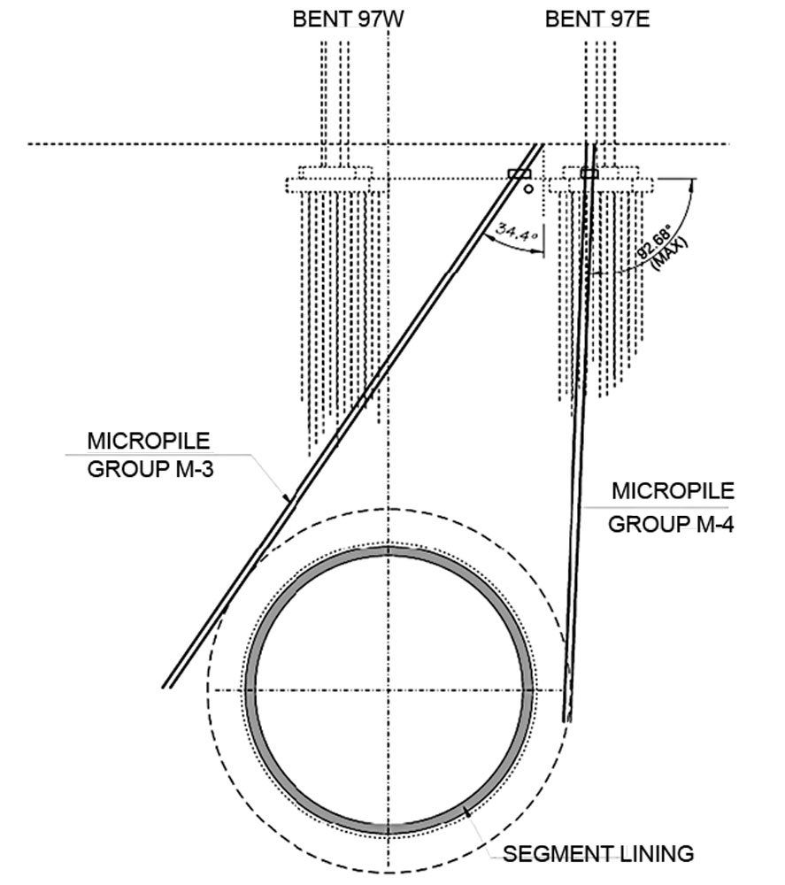
Figure 4. AWV settlement mitigation.
At the tunnel’s north end, the completion of the tunnel drive, the tunnel has sufficient overburden and a deeper water table so as not to require being held down by a box structure. The primary concern is mitigating against surface settlement. Settlement risk to existing buildings was mitigated with rows of protective micro-piles.
The tunnel’s interior structure is comprised of two continuous corbels supporting a series of 650-foot-long moment frame systems of walls and slabs, detailed to expand and contract longitudinally. The lower roadway walls are primarily pin connected to the corbels below and fixed to the upper roadway slab and traffic barriers above. The upper walls are pin connected on each end, detailed to accommodate transverse seismic deformation of the frame or tunnel ring. The electrical room and egress corridor slabs are cantilevered from the interior walls; the cantilevered slabs and upper roadway walls are clear of the tunnel ring sufficient to accommodate the anticipated ring ovaling due to seismic ground movement (Figure 5).
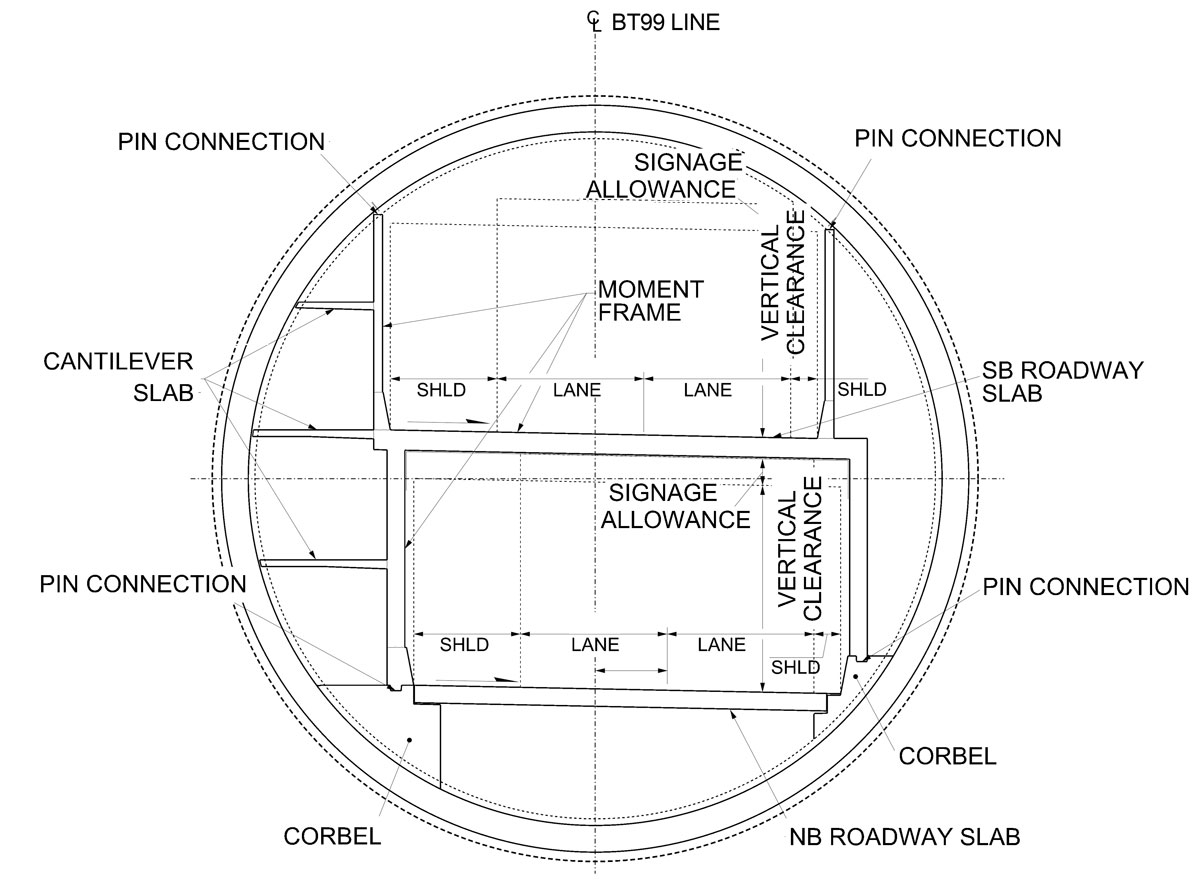
Figure 5. Section – Tunnel Interior Structure (TIS).
The tunnel ring and its interior structure were constructed in a factory-line style system. The TBM erected the ten precast ring segments as part of its excavation/advancement. Segment arrangement was dictated by the highway’s design alignment, as the ring’s profile was designed so the rotation of it would incrementally change the TBM’s heading. Workers on the tail of the TBM drilled corbel dowels into the ring segments at locators blocked out prior to casting. Behind the tail, workers installed a rail just inside each corbel face to support the traveling form system gantry. Carpenters built end-forms for each corbel in 50-foot intervals, the ring surface was prepped, corbel reinforcement cages were trucked in and placed, embedded conduits installed, and traveling forms were lowered into place and concrete pumped in by ready-mix trucks. All the while, the invert of the tunnel was kept free of obstructions for passage of the ring segment hauler and shift changes of workers (Figure 6).
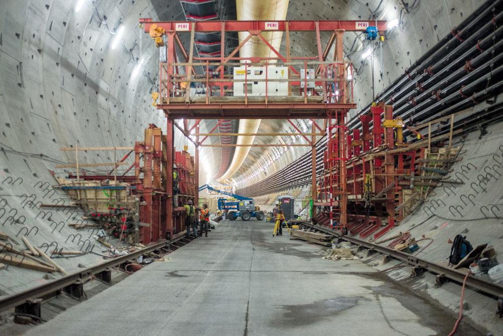
Figure 6. Tunnel interior structure corbel construction.
Construction of the walls was similar, with skip forming, pre-assembled reinforcing cages, and cast-in-place with a rail supported traveling formwork (Figure 7).
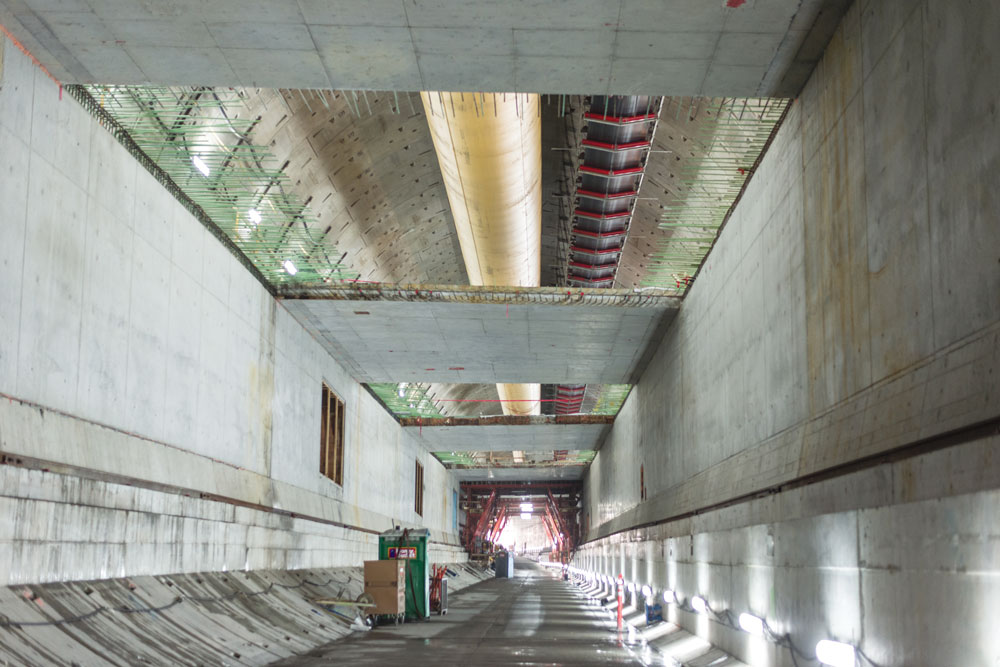
Figure 7. Skip forming for upper slab of interior structure.
Project success would not have been possible without an ability to design a permanent structure that could be built while not obstructing temporary work activity such as the TBM excavation removal, the ventilation duct below the crown, or material delivery along the invert (Figure 8).
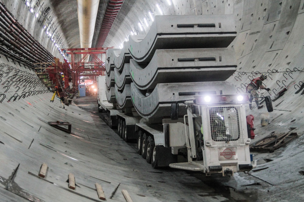
Figure 8. TBM delivery during TIS construction.
Conclusion
The SR 99 Bored Tunnel will open to traffic in February 2019, signifying the official completion of the project that began in 2011. The STP team had encountered and overcome enormous challenges in managing, designing, and constructing the project that included one of the largest and recording-setting bored tunnels in the world, and resulted in a significant and long-lasting infrastructure in Seattle that will be enjoyed by generations to come. The SR 99 Tunnel also opens areas that were occupied by AWV for improvement and affords Seattle the opportunity to make it a world-class waterfront city. Demolition and decommissioning of the Alaska Way Viaduct and construction of the new Alaskan Way street along the waterfront are scheduled to begin in early 2019.■