
In 1893, John A. L. Waddell (see bio in STRUCTURE, February 2007) designed, based on the designs of Squire Whipple, a lift bridge over the south branch of the Chicago River at South Halsted Street. Plans were made to replace a damaged swing bridge at the site with another swing bridge but the “lake navigation interests” objected, arguing that the old bridge was “always a serious obstruction to navigation.” Their argument was heard by the Corps of Engineers who ruled that they “would not permit him [the Commissioner of Public Works Aldrich] to build any structure which would narrow the water-way to such an extent as would a rotating draw span.”A vertical lift bridge was then considered, along with bascule spans. Waddell wrote a paper on the design of his bridge on November 16, 1894, and it was published in the 1895 Transactions ASCE. He introduced the paper by describing the problems he had in getting his design accepted. He wrote,
“After making a thorough study of the problem, Mr. Aldrich decided upon building a lift-bridge similar to the one designed previously by the writer for the proposed crossing of the ship canal at Duluth; and after considerable delay permission was obtained from the War Department to build the structure, with the proviso, however, that the clear headway be increased from 140 to 155 feet above mean low water…
But it was not until the beginning of 1893 that the contract for building the bridge was finally signed, sealed, and delivered. Even then the tribulations of those interested in the enterprise were not at an end, for the letting of the contract was irregular, in that there was no money in the City Treasury to pay for the bridge; therefore, according to the usual custom under such conditions, reliance was placed on the Finance Committee and Board of Aldermen voting, later on, the necessary funds. Under ordinary circumstances this irregularity would have done no harm; but in this case it was otherwise, because it gave each Alderman and each city official an opportunity to tie up the work, if he so desired, by alleging that the scheme was impracticable and that the bridge could not possibly work successfully…
Another main cause of difficulty and delay was the continual changing of city officials, for in the two years during which this bridge subject was on the tapis there were three changes of administration, involving the election or appointment of three Mayors, three Commissioners of Public Works, and three City Engineers, to say nothing of minor officials.”
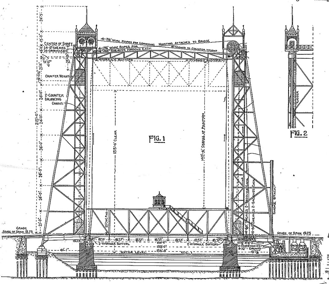
Portion of plate showing lift span in a closed position and an open position – dotted lines.
He then described the bridge utilizing many illustrations. He wrote,
“The bridge consists of a single Pratt truss through-span of 130 feet, in seven equal panels, and having a truss depth of 23 feet between centers of chord pins, so supported and constructed that it may be lifted vertically to a height of 155 feet clear above mean low water. At its lowest position, the clearance is about 15 feet, which is sufficient for the passage of tugs when their smokestacks are lowered. The span differs from ordinary bridges only in having provisions for attaching the sustaining and hoisting cables, guide rollers, etc., and in the inclination of the end posts, which are battered slightly, so as to bring their upper ends to the proper distance from the tower columns and their lower ends to the required positions on the piers.
At each side of the river is a strong, thoroughly braced, steel tower, about 217 feet high from the water to the top of the housing, exclusive of the flagpoles, carrying at its top four built-up steel and cast-iron sheaves, 12 feet in diameter, which turn on 12-inch axles. Over these sheaves pass the 4-inch steel wire ropes (32 inches all) which sustain the span. These ropes are double; i. e., two of them are brought together where the span is suspended, and the ends are fastened by clamps, as shown in Fig. 1; while, where they attach to the counterweights, they form a loop, which passes around a 15-inch wheel or pulley that acts as an equalizer in case the two adjacent ropes tend to stretch unequally.
The counterweights, which are intended just to balance the weight of the span, consist of a number of horizontal cast-iron blocks about 10 x 12 inches, in section, and 8 feet 7 inches long, strung on adjustable wrought-iron rods that are attached to the ends of rockers, at the middle of each of which is inserted the 15-inch equalizing wheel or pulley previously mentioned…
The bridge is designed to carry a double-track street railway, vehicles, and foot passengers… It has a clear roadway of 34 feet between the counterweight guides in the towers, the narrowest part of the structure, and two cantilevered sidewalks, each 7 feet in the clear, the distance between central planes of trusses being 40 feet, and the extreme width of suspended span 57 feet, except at the end panels, where it is increased gradually to 63 feet.”
Waddell wrote, “Chicago engineers as a body were opposed to this type of bridge; and the then highest authority on bridges in America, the late George S. Morison, stated flatly that it could not possibly operate and that it would be impracticable to raise the span off the piers. On the strength of this statement, the city Engineer made all the arrangements for canceling the contract for the construction although some of the substructure had been completed and a large proportion of the metalwork had been manufactured. It took some very earnest pleading by the writer to persuade him to permit the work to proceed, and the said pleading would have been unsuccessful had it not been for an important fact pointed out. Viz., that the city of Chicago would have had to pay the full contract price for the structure whether it were built or not.” The contract called for the bridge to be lifted in less than one minute while adjacent swing spans were taking over 2 minutes to open completely. Waddell also had to guarantee the proper functioning of the bridge.
The company building the lifting mechanism, with city backing, would not guarantee the operation using electric motors. Waddell designed the bridge with two 65 HP motors, mounted on the lift span, to provide the supplemental lifting power. Instead, he had to use two 78 HP steam engines located in a room below the approach roadway. Waddell had to consent to these changes to demonstrate the reliability and suitability of lift bridges in situations with large volumes of river traffic. He was promoting the fact that his bridges could be raised in under one minute only as necessary to provide safe passage by various height ships, while a swing bridge had to be fully opened for all shipping. He wrote, “On this score, though, he desired to make no complaint, for he was well content in having had an opportunity to prove the practicability of his lift-bridge designs, even with the accompanying irksome restrictions.” The contract to build the bridge was not signed until early 1893. After many financial problems and changes in city administration, the bridge was opened in late 1893. He wrote, “This was certainly a great triumph for a comparatively young engineer in a struggle with the local technical body, including the highest bridge authority in America.”
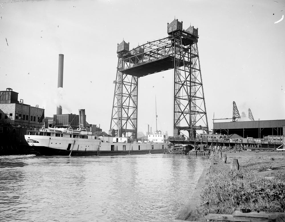
Halstead Bridge. Courtesy of Haer.
Waddell’s article also included portions of his specifications and additions by T.W. Heerman’s on the operating machinery, Samuel Rowe on miscellaneous matters associated with the bridge, and W. W. Curtis on the erection of the bridge. It also was discussed by several engineers at the meeting at which it was presented, and later by several other written discussions. They were generally positive, but many thought the bridge was costly to build and operate and would not be competitive with swing or bascule spans.
Waddell listed the advantages of a lift span over a swing span as follows:
“1st. A lift-bridge gives one wide channel for vessels instead of the two narrow ones afforded by a center-pivoted swing-bridge.
2d. There are no land damages in the case of a lift-bridge, as the whole structure is confined to the width of the street. These land damages in the case of some swing-bridges amount to a large percentage of the total cost of structure.
3d. Vessels can lie at the docks close to a lift-bridge, which they cannot do in the case of a swing-bridge; consequently, with the former, the dock front can be made available for a much greater length between streets than it can with the latter.
4th. The time of operation for a lift-bridge is about 30% less than that for a corresponding swing-bridge.”
These were the same arguments Whipple made in support of his Hotel Street Bridge in Utica, New York. Waddell concluded his paper writing, “If the contract for building a duplicate of the Halsted Street lift-bridge were to be let today, at present prices, with close competition, and if the engineer were allowed full sway in making plans and specifications for substructure, superstructure, approaches, and machinery, based upon correct data, it is not too much to say that the entire cost would be reduced to, at most, $150,000, instead of $200,000, which is about what the structure itself would cost, exclusive of outside extras.”
After the bridge opened and had been operating for a while, Waddell indicated that in the future, if he had “carte blanche in the designing, he would, based upon his experience on this initial lift span, make the following improvements,”
- Curve the rear column and arch the overhead girders at the tops of towers so as to improve the general appearance.
- Operate by electricity instead of by steam.
- Place the machinery house in one of the towers and dispense with the operating house on the span…
- Omit the water tanks as an unnecessary precaution and rely on the great capacity of the electric motors to overcome any temporary unbalanced load.
- A simpler and less expensive adjustment at feet of rear columns.
- Cast steel instead of cast iron for all machinery.
- Catch the balancing chains in buckets placed on top of the span instead of hanging them to the counterweights.
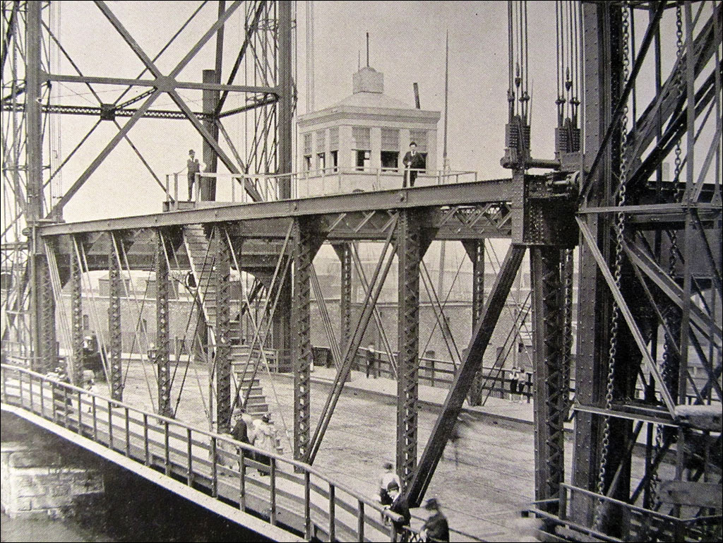
Halsted Street, view of lifting span with a control tower on top of the span.
With the bridge opening and successful operation, even though expensive due to the use of steam engines to supply power, the era of the long span, high lift, vertical lift bridge slowly began. It was impressive, as a first attempt, that the bridge was so successful and had considered so many of the features that were to become a part of most future lift spans. Waddell would not, however, build another lift span for many years, as many of his colleagues viewed it as an expensive solution. John L. Harrington, who became Waddell’s partner in the future, wrote, “The principal details of the structure are not unusual. It is the idea, the design as a whole that is novel. The great height of the structure and the great weight to be lifted were adversely criticized by engineers and laymen alike; but, while a better type of movable bridge suitable for the conditions which governed the design of the Halsted Street Lift-Bridge has since been developed, there was nothing better in that day. All things considered, it is a substantial and creditable piece of work which will serve its purpose admirably for many years to come.”
Waddell went on to design and build many vertical lift bridges around the United States. He and Harrington received several patents that gave the firm of Waddell & Harrington a near monopoly on this style of bridge for years.■