
In 2016, AISI S100, North American Specification for the Design of Cold-Formed Steel Structural Members (or Specification), was updated with an entirely new layout which is parallel in format with ANSI/AISC 360, Specification for Structural Steel Buildings. Also, the Direct Strength Method has been integrated into the body of AISI S100, which enables engineers to design cold-formed steel members with unconventional cross-sections. This reorganized Specification emphasizes design in the main body with the more involved calculations moved into the appendices, such as determination of effective widths and buckling equations for complex sections. A more detailed section-by-section cross-reference between the 2012 edition and the new edition is provided at the beginning of the Standard. An outline of the general steps to determine member strengths is also provided. This article introduces the reorganized Specification, chapter-by-chapter, to familiarize engineers with the new layout and point out the significant changes in the new edition.
Chapter A, Scope, Applicability, and Definitions. This chapter outlines the scope and applicability of the Specification: cold-formed steel structural members can be designed using AISI S100-16 through the design provisions provided in the Specification (excluding those in Chapter K). However, if the composition or configuration is beyond those design provisions, the member strength can be determined by tests, by rational engineering analysis with confirmatory tests, or by rational engineering analysis with the following safety and resistance factors:
For members, Ω=2.00 (ASD); φ=0.80 (LRFD) or 0.75 (LSD)
For connections, Ω=3.00 (ASD); φ=0.55 (LRFD) or 0.50 (LSD).
In this new edition, the above safety and resistance factors have been revised to provide better alignment between the testing provisions and the provisions for rational engineering analysis.
Chapter B, Design Requirements. This chapter lists the essential design requirements: design for strength, structural members, connections, stability, structural assemblies and systems, serviceability, ponding, fatigue, and corrosion effects. The Specification also points to the appropriate chapters or sections for the design provisions. In addition, the application limitations for the Effective Width Method (EWM) and the Direct Strength Method (DSM) are provided, and these limitations are consolidated and greatly simplified.
Chapter C, Design for Stability. This chapter includes design provisions for considering structural system stability and member stability. It is required that the structural system stability be considered in accordance with Section C1. The provisions provided in Section C1 are developed based on the AISC Direct Analysis Method, which requires that the whole structure be analyzed, and members and connections designed, with the following effects considered:
- Flexural, shear, and axial member deformations, and all other component and connection deformations that contribute to displacements of the structure;
- Second-order effects (including P-Δ and P-δ effects);
- Geometric imperfections;
- Stiffness reductions due to inelasticity, including the effect of residual stress and partial yielding of the cross-section;
- Stiffness reduction due to cross-section deformation, or local and distortional buckling;
- Uncertainty in the system, member, and connection stiffness and strength.
Three approaches are permitted:
a) Direct Analysis Method Using Rigorous Second-Order Elastic Analysis: Determines the required strengths which include the both P-Δ and P-δ effects, initial imperfections and adjustment of stiffness. The available strengths are then determined using the Specification provisions with the effective length factors, Ky and Kx, equal to one.
b) Direct Analysis Method Using First-Order Analysis: Determines the required strength by considering initial imperfections and adjustment of stiffness in the structural analysis. Both P-Δ and P-δ effects are considered using multipliers B1 and B2 (as provided in Specification Equations C1.2.1.1-3 and C1.2.1.1-6). The available strengths are determined as described in (a) above. This method is limited to structures that support gravity loads primarily through nominally vertical columns, walls or frames.
c) Effective Length Method: Determines the required strength through linear elastic analysis. The P-Δ and P-δ effects are considered by applying the effective length factors to members when the available strengths are calculated. This method is limited to structures that (i) support gravity loads primarily through nominally vertical columns, walls or frames; and (ii) the maximum second-order drift does not exceed 1.5 times the maximum first order drift.
Chapter D, Members in Tension. This chapter includes tension member design provisions similar to those in the previous Specification edition.
Chapter E, Members in Compression. The column member design provisions consider the following possible failure modes: yielding and global buckling, local buckling interacting with yielding and global buckling, and distortional buckling. Both the EWM and the DSM can be used for the design. For members with holes, comprehensive design provisions are provided with the DSM approach.
Chapter F, Members in Flexure. Similar to column member design, flexural member design also considers yielding and global buckling, local buckling interacting with yielding and global buckling, and distortional buckling. For flexural members, provisions are provided to determine the inelastic reserve capacities when members are not subject to local or distortional buckling. The provisions for flexural members with holes are also provided with the DSM approach.
Chapter G, Members in Shear and Web Crippling. This chapter determines the shear strengths of members with or without holes, with or without web stiffeners, and web crippling strengths.
Chapter H, Members Under Combined Forces. This chapter includes the following interaction checks for members subjected to combined forces:
- Combined tensile axial load and bending; and combined compressive axial load and bending
- Combined bending and shear
- Combined bending and web crippling
- Combined bending and torsional loading
In this edition, the interaction equations for ASD, LRFD, and LSD are unified wherever possible.
Chapter I, Assemblies and Systems. This chapter contains the design provisions included in Chapter D of the previous Specification editions. The following changes and additions were made:
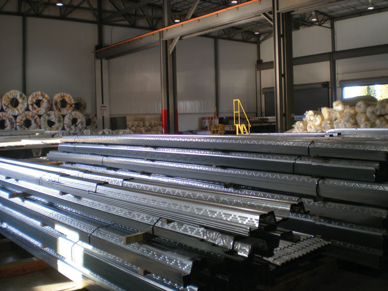
Figure 1. Example of a profiled deck.
- 1) For floor, roof, or wall steel diaphragm construction, three AISI standards are referenced for different applications:
a) AISI S310, North American Standard for the Design of Profiled Steel Diaphragm Panels, should be applied for diaphragms and wall diaphragms constructed with profiled steel panels and decks (Figure 1). The safety and resistance factors for this type of diaphragm systems have been moved from the Specification to AISI S310.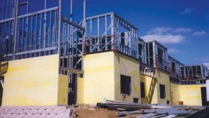
Figure 2. Cold-Formed steel framing with structural wood sheathing.
b) AISI S240, North American Standard for Cold-Formed Steel Structural Framing, should be used for diaphragms constructed with wood structural panels, shear walls covered with flat steel sheets, wood structural panels, gypsum boards or fiberboard panels, or strap braced cold-formed steel stud walls (Figure 2).
c) AISI S400, North American Standard for Seismic Design of Cold-Formed Steel Structural Systems, should be followed for additional seismic design requirements. - For cold-formed steel light frame construction (Figure 2):
a) AISI S240 should be followed for framings subjected to gravity and wind loads; and
b) AISI S400 should be considered in high seismic load design (Seismic Design Category greater than A) and the seismic modification factor, R, not equal 3.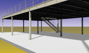
Figure 3. Special bolted moment frame.
- For special bolted moment frames (Figure 3) under seismic loads, AISI S400 should be followed.

Figure 4. Metal building system.
- For metal roof and wall systems (Figure 4), the compressive and flexural strengths of members covered with metal roof and wall panels can now be determined analytically through the DSM approach where the buckling forces or moments should be determined including lateral, rotational, and composite stiffness provided by the metal deck or sheathing; bridging and bracing; and span continuity. These added provisions would enable engineers to design systems that may be outside the limitations of the empirical equations.
- For steel rack system design, ANSI MH16.1 is referenced.


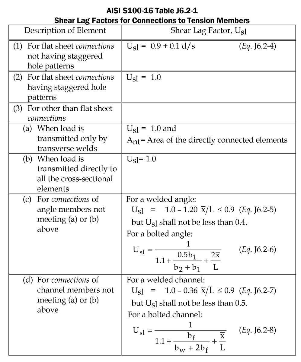
Chapter J, Connections and Joints. This chapter contains all the design provisions included in Chapter E of the previous Specification editions. The tension rupture provisions for a single bolt, or a single row having multiple bolts perpendicular to the force, are revised. As shown in AISI S100 Table J6.2-1, the revised provisions contain a single shear lag reduction factor for all flat sheet bolted connections not having staggered hole patterns. The reduction factors for bolted connections of angle or channel members are specified as well in Specification Eqs. J6.2-6 and J6.2-8. Also, design references for cold-formed steel connecting to hot-rolled steel, aluminum, concrete, masonry, wood, and plywood are added to Commentary Section J7. These design provisions and references are deemed proper for determining connection strengths when other materials control the strength.
Chapter K, Strength for Special Cases. This chapter includes the complete list of AISI test standards, and the provisions to determine the structural performance (strengths) via tests or via rational engineering analysis with confirmatory tests. In this edition, the Statistical Data for the Determination of Resistance Factor (as shown in AISI S100 Table K2.1.1-1) have been consolidated and greatly simplified. For diaphragm formed by profiled steel panels, the tests should be in accordance with AISI S310.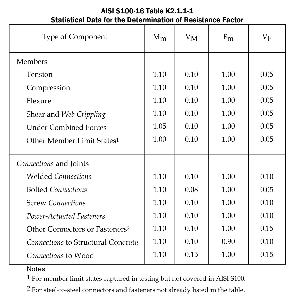
Chapter L, Design for Serviceability. This chapter includes the provisions for determining the moment of inertias used in serviceability calculations. The flange curling checks are included in this chapter. A rational approach is introduced in the Commentary when DSM is used.
Chapter M, Design for Fatigue. This chapter contains the fatigue design provisions similar to those in the previous Specification edition.
Appendix 1, Effective Width of Elements. This appendix contains all the provisions for determining the effective widths under different edge conditions and stress distributions, which were included in Chapter B of the previous Specification edition.
Appendix 2, Elastic Buckling Analysis of Members. This appendix provides information and references needed to determine the member buckling stresses or stress resultants with either numerical or analytical approach. These buckling stresses or resultants are used throughout Chapters C to H.
Appendix A, Provisions Applicable to the United States and Mexico. This appendix includes the provisions that are applicable to the United States and Mexico only. In this edition, the country-specific provisions are consolidated or eliminated wherever possible.
Appendix B, Provisions Applicable to Canada. This appendix includes the provisions that apply to Canada only.
In addition to updating AISI S100-16, AISI cold-formed steel framing standards were updated in 2015. Users can download all AISI newly published standards from the website www.aisistandards.org. To help design engineers better understand AISI S100-16, the companion document, AISI Cold-Formed Steel Design Manual, has been updated and published in 2018. This new edition of the Design Manual provides design examples that illustrate the newly added design provisions.■
A similar article was published in Proceeding of Twenty-Third International Specialty Conference on Cold-Formed Steel Structure. Content is reprinted with permission.
References
- ANSI/AISC 360-10, Specification for Structural Steel Buildings, 2012 Edition.
- AISI S310-16, North American Standard for the Design of Profiled Steel Diaphragm Panels
- AISI S240-15, North American Standard for Cold-Formed Steel Structural Framing
- AISI S400-15, North American Standard for Seismic Design of Cold-Formed Steel Structural Systems
- ANSI MH16.1-12, Specification for the Design, Testing, and Utilization of Industrial Steel Storage Racks, 2012.
- Schafer, B.W., H. Chen, B.E. Manley and J.W. Larson (2015), Enabling Cold-Formed Steel System Design Through New AISI Standards, ASCE Proceeding Structures Congress 2015.
- Roger LaBoube, Jay Larson and Helen Chen (2017), Cold-Formed Steel Framing Standards Updated for 2018 IBC, STRUCTURE, November 2017.
Outline for Determining Member Strengths:
- Determine member axial force and bending moment:
• Use any one of the three approaches provided in Section C1 to consider the P-Δ and P-δ effects (provided the requirements for the corresponding approach are met.) - For tension members:
• Tension member strength is determined in accordance with Chapter D. - For compression members:
• Compression member strength is the smallest one of the following three strengths:
i. Strength considering yielding and global buckling per Section E2.
ii. Strength considering local buckling with yielding and global buckling per Section E3.
iii. Strength considering distortional buckling per Section E4. - For bending members:
• Bending member strength is the smallest one of the following three strengths:
i. Strength considering yielding and global buckling per Section F2.
ii. Strength considering local buckling with yielding and global buckling per Section F3.
iii. Strength considering distortional buckling per Section F4.
• Shear strength:
i. Shear strength without holes per Section G2.
ii. Shear strength with holes per Section G3.
• Web crippling strength per Section G5. - For members subject to combined forces, check combined force actions per Chapter H
- For built-up members, the connections should be designed per Section I1.