
Base plate design” is a frequently misunderstood term, particularly when discussing attachments for post-installed anchoring applications. This article explains how the concept of base plate design, which is typically understood in the context of “column base plate design,” is not necessarily relevant to fixture attachment for post-installed anchoring applications.
Typical Base Plate Design
The term base plate is commonly understood as referencing a steel plate placed beneath a column to distribute applied loads to a concrete member. The plate is assumed to act as a cantilever beam fixed at the edges of the column, defined by the geometry of a structural profile (Figure 1). If a wide-flange section is used as a column, the base plate design can be summarized as follows:
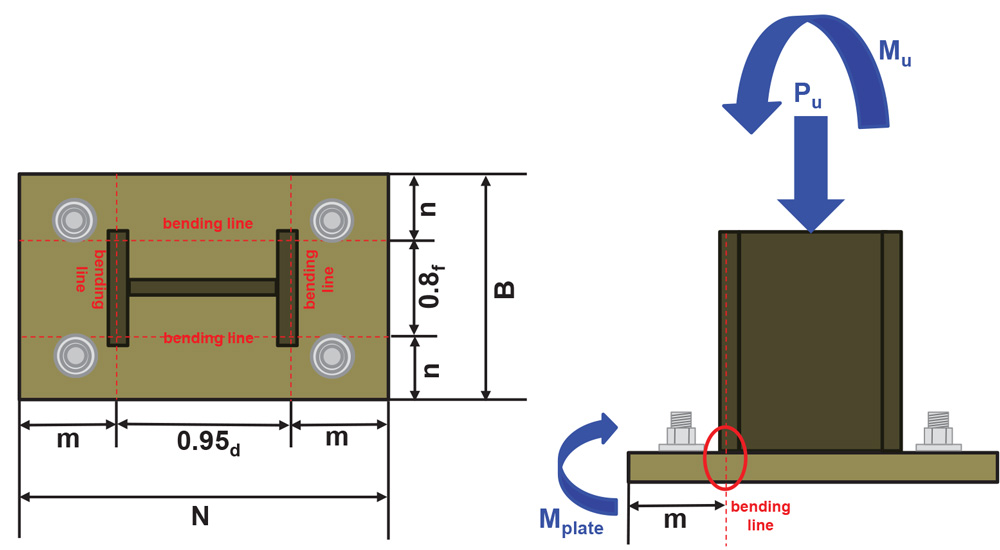
Figure 1. Column base plate design parameters.
- Select a plate length (N) and width (B).
- Check the concrete bearing capacity using these plate dimensions.
- Plate bending can be assumed to occur at the cantilevered plate sections defined by the parameters (m) and (n).
- Calculate the plate thickness (tp) via the internal bending moments assumed to occur at each cantilevered section of the plate
Column base plate design assumes the plate is rigid. In other words, the plate cross-section remains plane under loading, and the plate does not undergo any significant deformation from bending. Although no plate is ever truly rigid, it is reasonable to assume a column base plate is rigid. This is because typical column base plate geometry precludes any significant plate deformation or bending under loading. The rigid plate assumption permits the stress/strain behavior of the anchor bolts and the concrete to be modeled as elastic. An elastic stress/strain model permits a linear analysis to be used in determining the compression stress in the concrete under the plate (σconcrete), the tension loads acting on the anchor bolts (Tanchor), and the internal bending moments used to calculate the plate thickness (Figure 2).
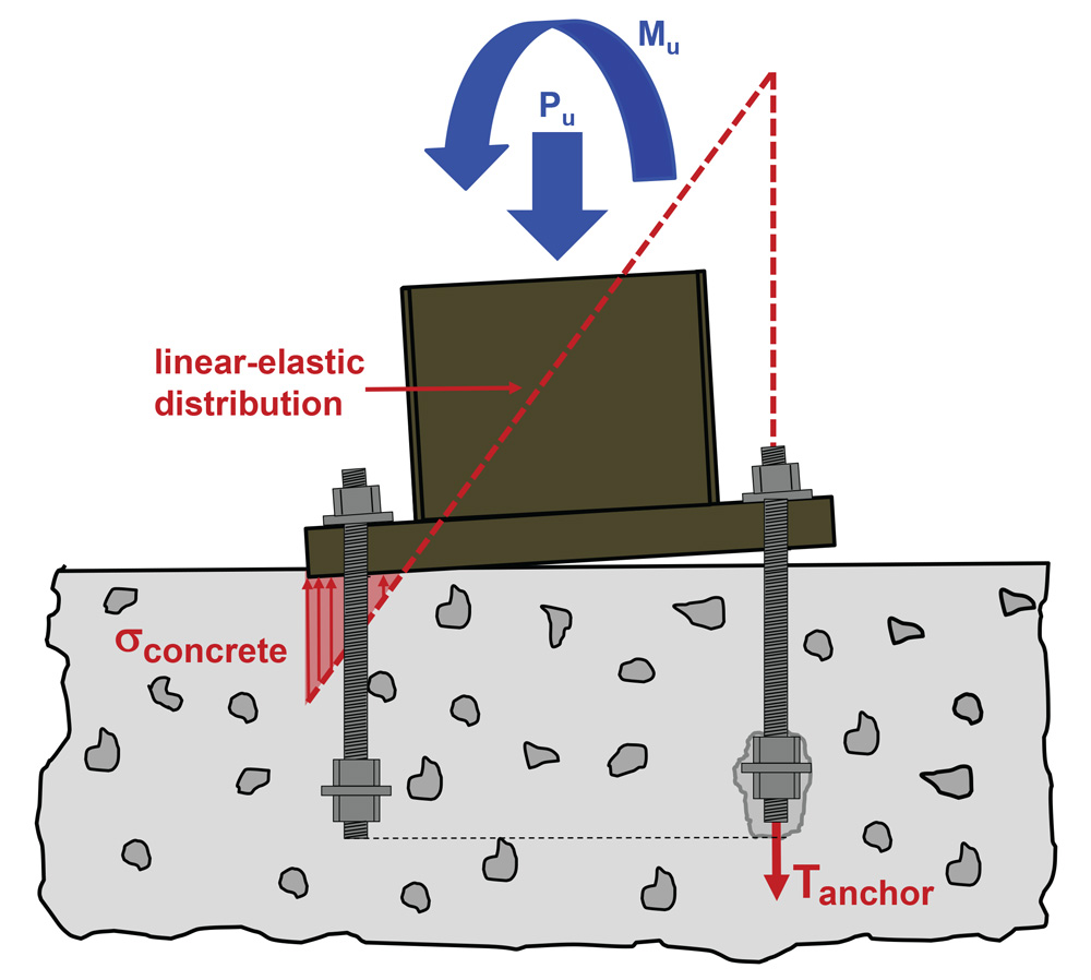
Figure 2. Rigid assumption uses a linear-elastic strain/strain model.
Typical column base plate design involves large axial compression loads, possibly acting in conjunction with an externally applied moment. Column anchor bolts are subjected to tension if the applied loads/moments create uplift on the column. It is possible for no tension loads to act on the anchor bolts if the column is subjected to pure axial compression or axial compression with a small external moment. Sometimes, column anchor bolts may only be used for erection to comply with Occupational Safety and Health Administration (OSHA) requirements. Column anchor bolt design can be predicated on the steel strength of a ductile anchor element, or on brittle failure modes such as concrete breakout. Column base plate design for shear loads can include shear load acting directly on anchor bolts, but it can also preclude shear load acting on the anchors through the use of shear lugs or embedding the column base into concrete. It is also possible that gravity load acting on the column creates enough frictional resistance between the base plate and concrete surface to preclude any direct shear load acting on the anchors.
Fixture Attachment
Column base plate attachment is not a typical post-installed anchoring application. Typically, post-installed anchors are used to attach a “fixture” such as a ledger angle, equipment support, handrail support, or plate. The loads acting on these fixtures are much smaller compared to typical column loads, and the anchors used to attach these fixtures are more likely to be subjected to direct tension and shear loads rather than compression loads. Furthermore, post-installed anchorage designs controlled by the steel strength of the anchors are typically not achievable.
Generally speaking, the fixture stiffness is assumed to be greater than the post-installed anchor stiffness, thereby permitting a rigid fixture design assumption that uses a linear analysis to calculate the tension loads acting on the anchors. These loads can then be checked against calculated anchor tension design strengths. The American Concrete Institute (ACI) standard ACI 318, Building Code Requirements for Structural Concrete, includes provisions for calculating post-installed and cast-in-place anchor design strengths. The parameters given in ACI 318 for calculating these anchor design strengths are derived from testing with a fixture that has a greater stiffness than the stiffness of the anchors; in other words, the fixture can be considered “rigid.” Therefore, a fundamental assumption when designing any anchorage using ACI 318 anchoring-to-concrete provisions is that the fixture being attached is rigid (Figure 3).
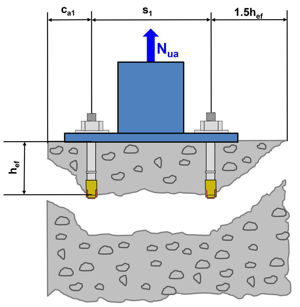
Figure 3. Anchoring-to-concrete provisions assume fixture is rigid.
Software that performs ACI 318 anchoring-to-concrete calculations is readily available. Many software packages perform what they term “base plate calculations,” but clarification is necessary as to the type of calculations actually being performed. Anchor design software typically performs calculations to determine the magnitude of the tension load acting on each anchor determined to be in tension, and the magnitude of the shear load acting on each anchor determined to be in shear. These loads are then checked against anchor design strengths calculated using ACI 318 anchoring-to-concrete provisions.
Anchor design software does not perform base plate design in the context of column base plate design. Instead, fixture dimensions are utilized in conjunction with loads and moments acting on the fixture to calculate resultant loads acting on the anchors. The fixture is assumed to be rigid, permitting a linear elastic stress/strain distribution to be utilized in conjunction with compatibility equations and statics to calculate the resultant loads. Individual anchor tension loads can be calculated once the resultant tension load is known. Tension eccentricity parameters are calculated if the resultant tension load is eccentric with respect to the anchors in tension. Concrete compression stress beneath the fixture is calculated, but no analysis of concrete bearing strength with respect to axial compression load is performed. Shear calculations do not check if the fixture thickness is sufficient to transfer shear loads into the anchors.
Typical anchor design software functionality can be summarized as follows:
- Locate the neutral axis of the fixture using a rigid assumption.
- Determine the compression stress in the concrete beneath the fixture based on the rigid assumption.
- Determine the resultant tension and resultant compression loads acting on the anchors based on the rigid assumption.
- Determine the load distribution on the anchors in tension based on the rigid assumption.
- Determine the eccentricity of the resultant tension load with respect to the center of gravity for the anchors that are in tension based on the rigid assumption.
It is important to realize what typical anchor design software calculations do not consider.
- No check is performed to determine if the rigid fixture assumption is valid. If the fixture is rigid, a linear elastic stress/strain distribution can be used to calculate tension loads on the anchors. The fixture thickness is important in ascertaining if a rigid assumption is valid. Software that permits users to input any fixture thickness, or utilizes a “minimum required” thickness to perform a linear-elastic analysis, is not validating if the fixture is rigid. The minimum required fixture thickness in anchor design software is used to dimension the nodes for a finite element rigid analysis. Most software packages permit this minimum thickness to be waived, and any thickness to be input.
- Stiffness parameters relative to a profile shape attached to the fixture are not considered. Software users can typically input any profile shape, or no profile shape, and the calculated tension loads on the anchors are independent of any stiffness parameters relative to the profile.
- The bearing strength of the concrete is not checked. Column base plates are sized to minimize the bearing stress on the concrete. Only the compression stress in the concrete beneath the fixture relative to the location of the neutral axis is considered.
What parameters, with respect to a rigid versus non-rigid fixture, should be considered for typical post-installed anchoring attachments involving a ledger angle, equipment support, handrail support, plate, etc.? If a rigid fixture assumption is valid, then the tension loads acting on the anchors can be calculated using a linear-elastic model, and anchor tension design strengths can be calculated using ACI 318 anchoring-to-concrete provisions. If the analysis indicates that a rigid fixture assumption is not valid, the fixture must be modified or re-designed to be rigid or alternative anchoring solutions must be considered.
A non-rigid fixture experiences non-linear tensile stress/strain behavior. Anchor tension loads calculated using a linear-elastic model may be significantly less than loads calculated using a non-linear model. A non-rigid fixture tends to re-distribute loads among anchors. Anchor design for a non-rigid fixture should ideally be controlled by ductile steel failure of the anchors to account for re-distribution of anchor loads. Anchor design, using ACI 318 anchoring-to-concrete provisions, does not consider parameters relevant to a non-rigid fixture. In particular, calculations that include a tension eccentricity modification factor could be unconservative if the fixture is not rigid because load re-distribution is not considered. Therefore, unless specific considerations are taken, anchor design using a non-rigid fixture can be unconservative in terms of the loads assumed to act on the anchors and the calculated anchor design strengths.
Design Approaches
When designing post-installed anchors, analysis to ascertain whether the fixture being attached should be considered rigid or non-rigid is relevant, but not always necessary. For example, it is reasonable to assume the fixture is rigid, without additional analysis, if the fixture can be considered unlikely to undergo significant deformation or bending for a given anchor configuration and embedment depth. For many post-installed anchoring applications, the relatively close anchor spacing and relatively shallow embedment depths at which the anchors are installed preclude significant fixture deformation or bending. However, assessing whether a rigid fixture assumption is valid becomes particularly relevant for applications that involve attachment of a thin fixture because parameters such as anchor geometry and installation, profile eccentricity, and fixture geometry could result in significant fixture deformation or bending taking place (Figure 4).
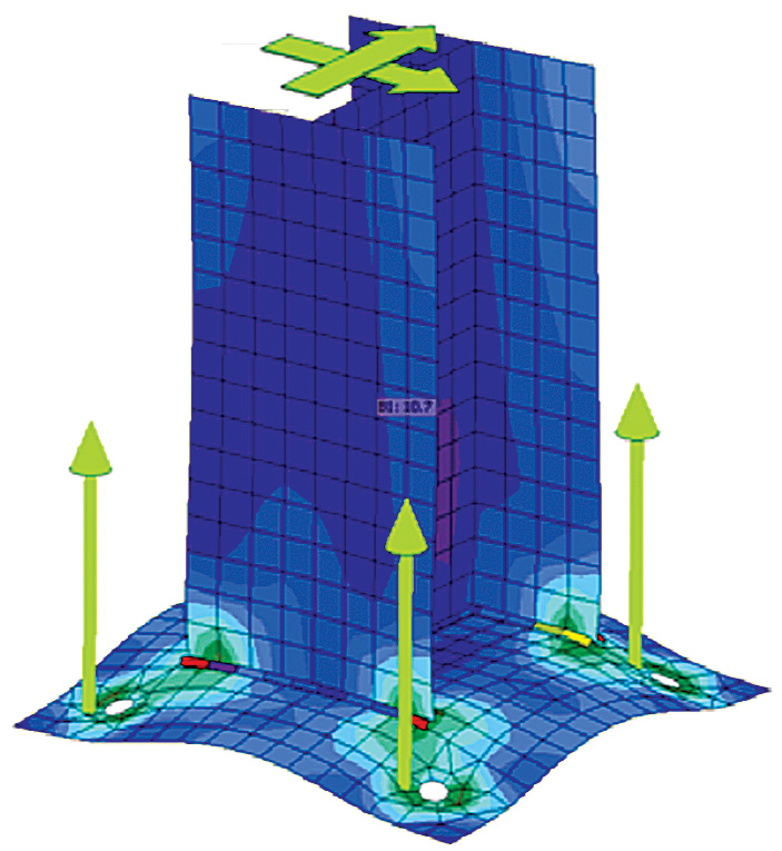
Figure 4. Finite element analysis for plate rigidity.
Courtesy of IDEA StatiCa.
Verifying that the stress in a fixture resulting from loading is less than the yield stress of the fixture is one parameter for determining if a rigid fixture assumption is valid. This parameter by itself, however, is not necessarily sufficient to determine if the rigid assumption is valid. Parameters relative to displacement must also be taken into consideration in order to validate a rigid fixture assumption. Post-installed anchor stiffness is defined by the parameter load/displacement and can be established via product testing. If the tension load acting on an anchor is known, and the anchor stiffness is known, the amount of displacement the anchor is anticipated to undergo can be calculated for a fastening application. Fixture displacement can be defined by the deflection that results from tension loads acting on the fixture, and from compression stress that develops between the fixture and concrete under loading. Its thickness influences fixture deflection. Increasing the fixture thickness can decrease the amount of deflection the fixture experiences. Therefore, determining the amount of stress in a fixture, the deflection it undergoes, and the amount of anchor displacement that results from a given loading condition provides a more in-depth assessment as to whether a rigid fixture assumption is valid.
Following are suggestions for ascertaining whether a rigid fixture assumption is valid.
Given:
- Fixture geometry, thickness, yield stress, modulus of elasticity (e.g., for a ledger angle or a plate)
- Structural profile geometry (if any) (e.g., structural tubing or equipment post)
- Anchor geometry, embedment depth, stiffness, and modulus of elasticity (e.g., for post-installed anchors)
- Concrete compressive strength and modulus of elasticity
- Tension load and/or moment acting on the fixture that results in tension loads on the anchors
- Check the maximum stress developed in the fixture (f fixture,max) versus the fixture yield stress (f fixture,yield).
a. If f fixture,max < f fixture,yield OK.
b. If f fixture,max > f fixture,yield Rigid assumption not valid. - Check fixture deflection caused by the tensile load (δfixture,tension) and fixture deflection caused by compressive load between the fixture and concrete surface (δfixture,compression). Set parameters for a limiting fixture deflection (δfixture,max) with respect to a rigid assumption.
a. If δfixture,tension and δfixture,compression
are < δfixture,max OK.
If δfixture,tension or δfixture,compression are > δfixture,max Rigid assumption not valid. - Check anchor displacement (δanchor) for the highest loaded anchor in tension. Set parameters for a limiting minimum displacement (δanchor,min) with respect to a rigid assumption based on anchor stiffness data. Maximum displacement is limited by anchor qualification test criteria.
a. If δanchor > δanchor,min OK.
b. If δanchor < δanchor,min Rigid assumption not valid.
If the analysis indicates that a rigid fixture assumption is not valid, an easy solution is to increase the fixture thickness. An alternative solution is to add stiffeners to make the fixture rigid. Typically, increasing the fixture thickness is more cost-effective than designing and fabricating stiffeners.
Whatever fixture thickness is used should also be checked to verify that it is adequate to transfer shear load into the anchors. This is a good design check because a thin fixture could tear. Minimum fixture thickness parameters for anchors subjected to shear loads should be established.
If designing a column base plate, verify that the concrete bearing strength is adequate for the fixture geometry and applied loads.
Once analysis indicates that a rigid fixture assumption is valid, anchor design for both tension and shear load conditions can proceed using ACI 318 anchoring-to-concrete provisions. The anchor capacities calculated with these provisions can be checked against the anchor loads calculated using the rigid analysis. As previously noted, tension design of anchors using ACI 318 anchoring-to-concrete provisions is predicated on the fixture being rigid. The fixture thickness established through a rigid analysis is also relevant to anchor calculations for shear load conditions. ACI 318 anchoring-to-concrete provisions for shear are predicated on the fixture having sufficient thickness to transfer applied shear loads into the anchors without tearing.
Summary
This article explained the differences between what can be termed “base plate design” and “fixture design,” primarily in the context of post-installed anchoring applications. Unlike most column base plates, fixtures attached with post-installed anchors may not be rigid and may, therefore, be subject to deformation and bending. A good design practice, particularly when considering attachment of a thin fixture, is to check whether a rigid fixture assumption is valid for that fixture. Assuming a fixture is rigid, when analysis might indicate otherwise, could lead to an unconservative anchorage design.▪