
The patients at Children’s National Health System’s main campus in Washington, D.C., needed fresh air. Going outside, however, is not always simple for hospitalized children, many of whom are not fully mobile or are connected to medical equipment. In addition, the hospital fronts a major urban avenue with little in the way of green space. In 2013, hearing of the significant logistical obstacles that hospital staff overcame to grant one terminally ill patient’s request to go outside, a donor stepped forward to turn the hospital’s long-held desire for a Healing Garden into reality. Additional donors joined in, including the foundation of the late philanthropist, horticulturist, and gardener Rachel “Bunny” Lambert Mellon. (Mellon oversaw the redesign of the Rose Garden and Jacqueline Kennedy Garden at the White House, elements of which are incorporated into the Healing Garden.) The result is now known as the Bunny Mellon Healing Garden dedicated to the First Ladies of the United States, in recognition of that venerable group’s longstanding commitment to Children’s National. However, before the garden could become a reality, the project’s structural engineer had to design structural strengthening to allow the conversion of the unoccupied roof to an outdoor respite for young patients and their families.
Existing Building
The building, originally constructed in the 1970s and expanded in subsequent decades, sits on a tight site. No suitable space for a garden exists at ground level, so the hospital proposed creating the garden on an existing 7,200 square-foot, unoccupied gravel ballasted roof located halfway up the six-story building. Surrounded on three sides by the building’s iconic sloped and mirrored walls, the garden opens on its fourth side to views of the U.S. Capitol and the National Mall.
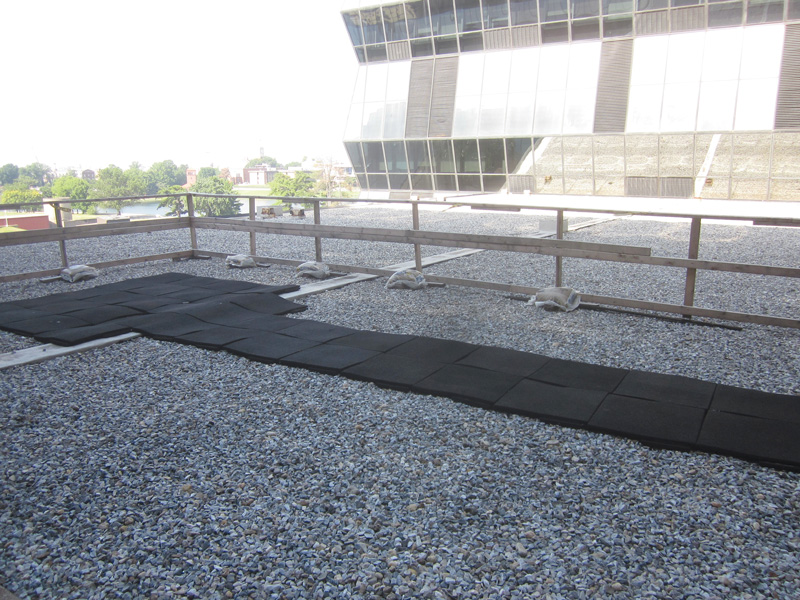
Roof before renovation.
The building portion located beneath the garden consists of full-story medical “use levels” alternating with half-story “interstitial levels,” each of which serves the use level below. Three pairs of 60-foot-long steel truss girders spaced at 30 feet on-center (o.c.) occupy the full 8-foot height of the interstitial level below the garden roof. Each truss consists of five 12-foot-wide sections, or panels, separated by web panel points. The trusses support roof framing on their top chords and interstitial-level framing on their bottom chords. At the roof level, steel beams support a concrete slab on composite metal deck and frame into the truss top chords at panel points. Half a story below at the interstitial level, steel beams spaced at 30 feet o.c. span to the building columns and the midpoints of the truss bottom chords and support a 7½-inch-deep cellular metal deck floor. The original structural drawings indicate that the roof structure was designed for a uniform live load of 100 psf to enable a future vertical building expansion. The interstitial levels were designed for a light live load for maintenance access plus a superimposed dead load to support hung ceilings and MEP components.
Design Approach
To support new roof garden dead loads in addition to a 100 psf live load, the roof structure would need to be strengthened. Internal scheduling constraints for the Healing Garden project meant that the hospital needed to secure a permit and begin construction of structural work before the final rooftop landscape design – including elements such as trees, planters, mounded soil, pavers, and concrete sitting walls – could be completed and approved. To allow the structural design to progress ahead of the landscape design, the design team and owner worked to establish roof loading parameters, evaluating a number of possible load layouts based on the weights of potential overburden materials and profiles. The studies culminated in the selection of a layout that balanced the vision for the garden with the need for an efficient and cost-effective structural strengthening scheme. The team agreed to locate the heaviest elements, including trees and a granite fountain, above existing columns and truss girders to limit the amount of strengthening. The structural engineer created a roof loading diagram for the permit drawings. The diagram specified locations of discrete elements such as trees and a tall cantilevered glass wall at the free edge of the roof; defined regions of heavy, medium, and light overburden loading; and listed maximum allowable superimposed dead loads for each region, ranging from 40 psf at the walking surfaces to more than 400 psf at the deepest planter boxes. The diagram also designated roof areas as either non-occupiable (e.g., at planter boxes) with an un-reducible design live load of 30 psf or occupiable (e.g., at walking surfaces and grass mounds) with a reducible design live load of 100 psf. This approach allowed construction of structural strengthening to begin before the architect finalized the rooftop design.
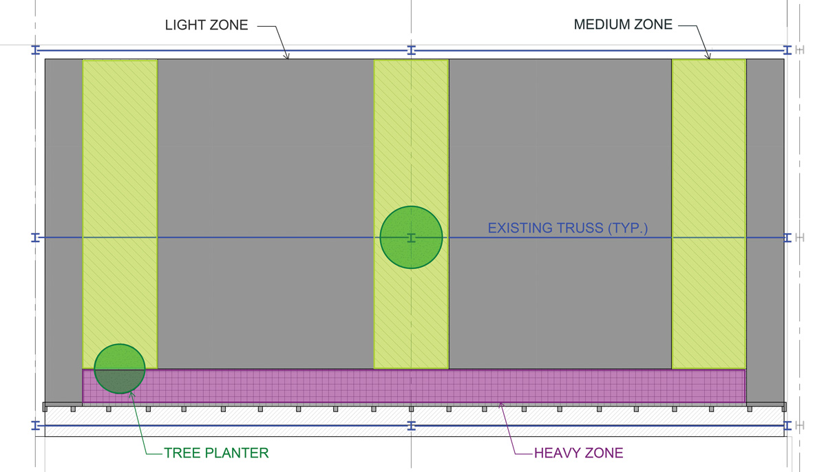
Overburden loading diagram.
Structural Challenges
The new overburden loads necessitated reinforcement of the existing roof slab, beams, and truss girders for strength and serviceability. Where needed, supplemental beams shortened the existing slab span, and new bottom flange plates stiffened existing beams. The truss girder strengthening was more complicated. The original building drawings included truss elevations with member sizes and design forces but did not provide detailed connection information for the truss joints. Original shop drawings were not available. Early in the design phase, the structural engineer entered the congested interstitial space with the contractor, who made localized probes in finishes for observation and documentation of existing truss framing members and connections. That upfront effort helped to reduce strengthening scope and cost since the engineer was able to calculate a higher capacity for the observed truss connections than the design forces published on the drawings.
Even so, the most highly loaded trusses required extensive modifications to the existing joints, including enlarging the connections by welding new gusset plates to the existing truss chords and webs.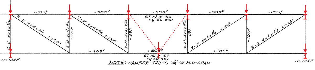
The overall truss geometry also required modification to support the new loads. At a typical original truss, configured as a hybrid Pratt/Vierendeel system, each of the four outer panels contains a single diagonal web member while the fifth, central panel remains open. The interstitial-level beams that frame into the midpoint of the truss bottom chord from each side support 900 square feet of deck in total and bear on the chord in the open central panel, delivering a concentrated load to the bottom chord halfway between panel points. Under the design interstitial floor and roof garden loads, the flexure induced in the truss bottom chord due to this configuration, combined with the chord forces due to overall truss behavior, would overstress the bottom chord. The truss strengthening scheme addressed this by adding new diagonal web members in a “V” shape within each center panel to create new panel points where the interstitial-level beams connect to the bottom chords.
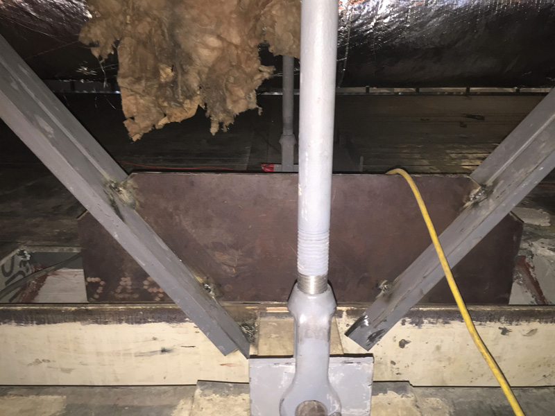
New truss V-Web with temporary hanger rod in the foreground.
To relieve the bottom chords of flexure while the new “V” webs were being constructed in the open truss panels, the structural engineer specified staged installation of temporary support framing. The steel erector installed hanger-rod-and-beam assemblies between the ends of the interstitial-level beams and the existing roof beams, then disconnected the ends of the interstitial-level beams from the bottom truss chords, temporarily rerouting the interstitial-level load from the truss chords to the roof beams at panel points. Following construction of the new panel points and installation of other truss strengthening elements, the erector reconnected the interstitial-level beams to the truss chords at the new panel points and removed the hanger rods. The structural engineer worked closely with the general contractor to ensure that the staged load transfer met the design intent.
Construction
Unique site constraints heightened the complexity of the contractor’s job. Working in a space with low clearance and many obstacles demanded unusual finesse and skill from the ironworkers and other subcontractors. Because the work area was located above a functioning laboratory and within a running hospital, the general contractor labored under strict noise, dust, and smoke control limits, installing temporary exhaust fans and a welding smoke evacuation system and covering existing air-handler intakes with carbon filters. Early exploratory work in the design phase minimized conflicts between existing and new ducts, pipes, and conduits and the new structural steel. Where unforeseen conditions did arise, the structural engineer and contractor collaborated to devise rapid solutions.
An Accessible Oasis
Major renovation projects, especially those that change the use of an existing space, can be primed for success when the owner, architect, and contractor recognize the value of involving the structural engineer early in the project and maintaining that engagement through assessment, design, and construction phases. Potential benefits of this approach include the following:
- The structural engineer can provide valuable information about the relative structural impact of the design concepts under consideration. In a green roof conversion project, that can help guide the landscape design of overburden materials and arrangements while controlling the amount of costly strengthening needed.
- By accessing and observing the configuration and condition of existing structural framing prior to designing modifications, the structural engineer can produce a more efficient design and minimize the likelihood of encountering unexpected conditions and conflicts during construction.
- In a project with complex site and programmatic constraints, collaboration between the structural engineer and contractor during the design and construction phases can establish an atmosphere of cooperation and facilitate constructible and creative design solutions.

Roof after renovation. Courtesy of Sam Kittner.
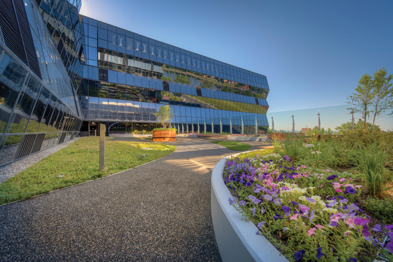
In April 2017, the Bunny Mellon Healing Garden dedicated to the First Ladies of the United States opened in a special ceremony featuring First Lady Melania Trump, family members of the late Bunny Mellon, and key supporters of the project. The garden, which is open year-round, is now a popular space for children and families at the hospital to play, relax, and reconnect with nature. In the end, the project’s architect, consultants, and general contractor all donated a portion of their services to the creation of the garden, and all are proud of the collaboration that helped to create an outdoor oasis for young patients in our nation’s capital.▪