
Those of you who have had an opportunity to work in jurisdictions that have adopted the 2015 International Building Code (IBC) should have noticed a significant change related to mandatory tornado shelters in a significant portion of the Central U.S. For areas that use the 2015 IBC, this new requirement will impact the majority of new school and emergency facility construction spanning as far north as central Minnesota, as far south as southern Mississippi, and stretching to western Pennsylvania in the east and western Texas to the west. This area is shown in Figure 1 and is where tornadoes with wind speeds of at least 250 mph have a history of occurrence.
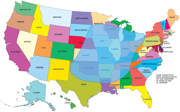
Figure 1. 250 MPH (402 Km/hr) tornado shelter zone per ICC 500-2014.
The IBC 2015 requires these tornado shelters be designed to meet the requirements of the 2014 ICC 500, Standard for the Design and Construction of Storm Shelters, and requires each shelter be designed to:
- be tornado debris impact resistant,
- resist wind speeds up to 250 mph,
- accommodate all the building occupants, and
- meet other requirements described in the ICC 500.
Impact Testing
Many schools and emergency facilities are constructed using masonry. This type of construction can be used to provide a safe, practical, and cost-effective solution for sheltering from tornados and high wind events. Therefore, it is important to understand what masonry wall configurations can be used to meet the required debris impact test for tornado shelters. It is imperative to note that all portions of the exterior envelope of tornado shelters must be able to meet the tornado debris impact test defined in the ICC 500 document and that these are more stringent than the requirements for hurricane impact testing.
As described in ICC 500, the exterior walls of all tornado shelters (of all material types) must be able to withstand three test “missile” impacts without penetration of the interior surface of the wall. The prescribed 2×4 wood missiles are 15 pounds in weight and are launched so that they are traveling at a minimum of 100 mph when they impact the wall segment being tested (Figure 2).
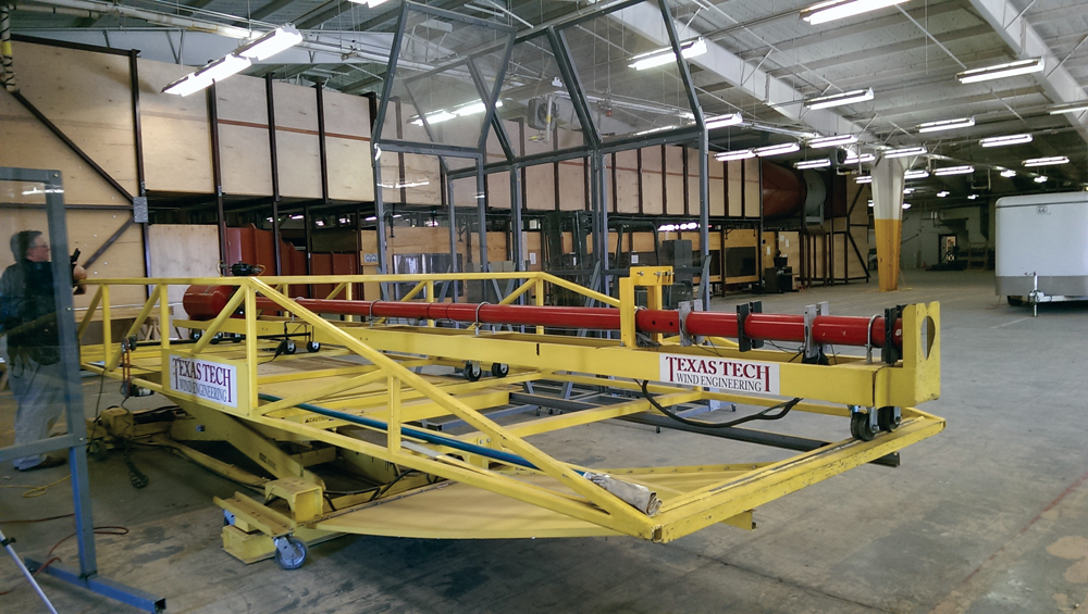
Figure 2. Tornado missile testing cannon.
Prior to 2014, only solidly grouted, single-wythe masonry walls systems were known to pass the tornado debris impact test. Designers had the option to use a single-wythe, solidly grouted wall, with or without a veneer. The expectation was the veneer, if used, would not contribute to the impact resistance and would be stripped away during the high wind event. In 2014, however, additional testing was done on partially grouted, cavity wall systems utilizing both the backup wall and the veneer to resist the missile impact. These tests opened additional masonry wall configurations for use in tornado sheltering applications.
New Testing
Because schools and emergency facilities frequently use partially grouted, masonry cavity walls (especially in the regions encompassing most of the ICC 500’s – 250 mph wind zone), questions were raised as to whether a masonry cavity could provide sufficient debris resistance, even if the backing wall was not fully grouted. A testing program was developed and executed as described below to answer the question.
Several questions needed to be addressed to arrive at a reasonable number of test specimens to prove the theory that partially reinforced and grouted CMU could effectively resist tornado missiles when covered with a brick veneer.
- Would the size of the brick veneer units influence impact resistance?
- Would a veneer of smaller units and more mortar joints behave differently than one with larger units and less mortar?
- As both modular and utility size brick units are commonly used for school cavity wall construction, these were tested to determine if the face size of the veneer unit and corresponding amount of mortar joints mattered.
- Would the reinforcing configuration of the partially reinforced CMU backup wall influence impact resistance?
- Would a closer spacing of the reinforced and grouted sections of wall influence impact resistances?
- As it is highly unlikely that a partially grouted CMU wall reinforced at vertical spacings of more than 32 inches would be able to resist the mandated ICC 500 tornado wind pressures, one of the test specimens used this reinforcing spacing in its backup wall. The second test specimen used a 24-inch-on-center backup wall reinforcing spacing if the larger spacing did not pass.
Cavity Wall Systems Tested
Two different wall configurations were developed and designed to be representative of clay brick and CMU cavity walls used in conventional exterior walls for schools. Figure 3 shows the first configuration. This wall specimen is consistent with common exterior school wall designs, with utility-size clay brick veneer, a 2-inch cavity, and an 8-inch partially grouted CMU backup wall. The CMU backup wall was reinforced vertically with #5, 60 ksi rebar, at 32 inches on-center. There was a bond beam cast at the top of the wall specimen to tie the specimen together. A heavy duty, 3⁄16-inch-diameter eye-and-pintel anchor system was used to attach the brick veneer to the backup wall; these anchors were spaced at 16 inches both vertically and horizontally. The specimens were constructed using ASTM C 90 CMU units, ASTM C 216 clay units, and ASTM C 270 Type S Masonry Cement Mortar. Fine grout was used, site-mixed based on the proportion specification of ASTM C 476.
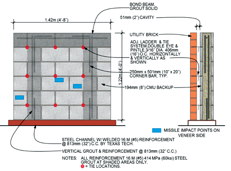
Figure 3. Cavity Wall Specimen 1 – utility brick.
Figure 4 shows the second specimen. Recognizing that more than one parameter was changing between the specimens, it was decided to change both brick size and reinforcement spacing on each specimen to gather the most information from this limited testing. This specimen was configured the same as the first, except that modular clay brick was used in the veneer and the vertical reinforcing spacing in the CMU backup wall was reduced to 24 inches.
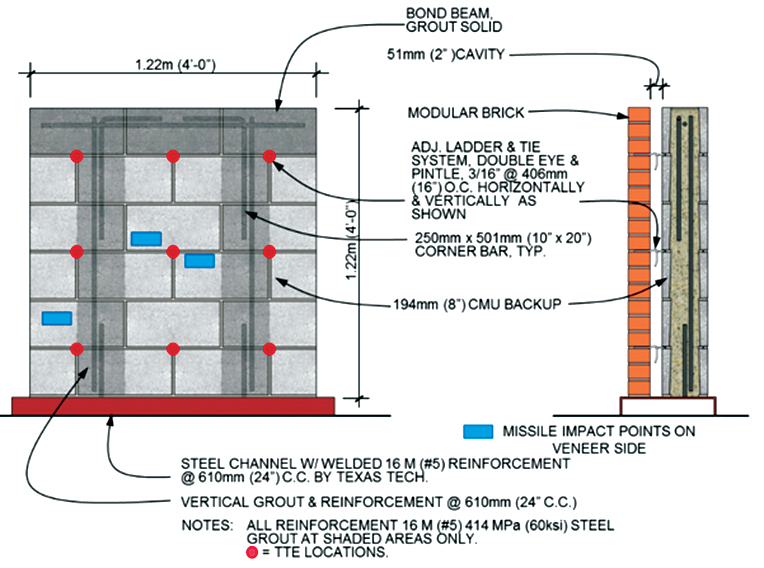
Figure 4. Cavity Wall Specimen 2 – modular brick.
Each of these specimens was tested at the Wind Testing Laboratory at Texas Tech University in Lubbock, Texas. The first specimen was placed in a missile testing apparatus, and a total of three, 15-pound 2 x 4 wood debris missiles were fired at the specimen at the prescribed speed required by the ICC 500.
The first missile strike was aimed at the middle of an ungrouted CMU core near mid-height and mid-width of the specimen. Figure 5 shows that, upon impact, the 2 x 4 missile shattered the clay brick veneer units at the missile impact location, passed through the brick veneer, and bounced off the cavity-side surface of the CMU backup wall with no damage noted. Two additional missiles were fired at this specimen; one missile was directed to the lower outer edge of the vertically grouted CMU cores on the right side of the specimen, and one missile was directed to the inner edge of the vertically grouted CMU cores on the left side of the specimen. Similar behavior was observed in all the impacts – the missile shattering the brick, pushing the brick pieces against the CMU face, and rebounding without causing any damage to the CMU wall. In all three tests, brick veneer was damaged (but repairable) and there was no visible damage to the CMU backup wall. Furthermore, upon careful inspection, there was no visible cracking or no missile penetration of the interior face of the CMU wall.
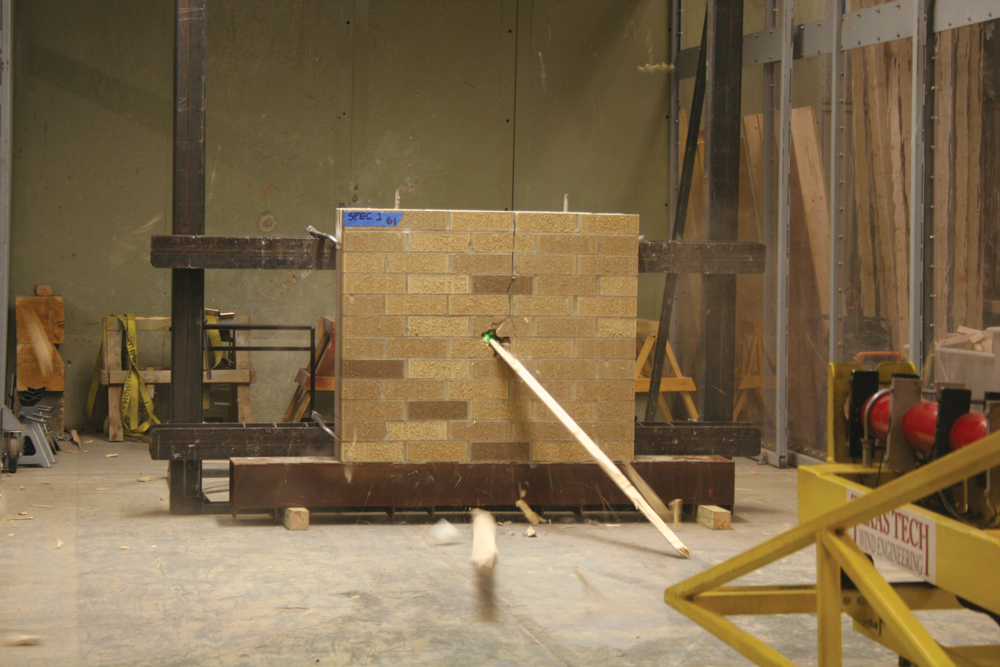
Figure 5. A first missile strike on Cavity Wall Specimen 1.
The above tests were repeated for Cavity Wall Specimen 2 (modular clay brick veneer and closer spaced vertical reinforcement). The results mirrored those of Cavity Wall Specimen 1.
The results of these tests clearly show that the brick veneer absorbs a significant amount of the missile’s energy. The shattering of the clay brick unit, the presence of the air cavity between the veneer and backup wall, and the ductile failure of the 3⁄16-inch diameter wire anchors reduced the backup wall strike energy to levels low enough that the ungrouted sections of the partially grouted CMU backup are able to resist the missile impact with no visible interior damage (Figure 6). Thus, the two brick-veneer and partially grouted CMU cavity wall configurations tested were deemed to have passed the code-mandated, tornado debris impact testing requirement. Even though the outer veneer is damaged in the location of impact, the missiles did not penetrate to the interior face. It should be noted that the veneer damage would be easily repairable after the wind event.
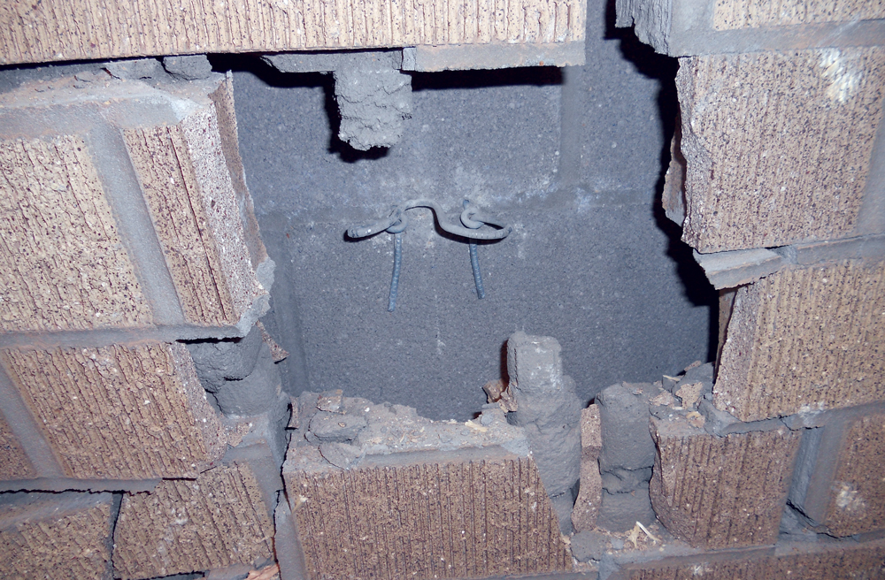
Figure 6. CMU surface behind missile strike on the Utility Unit Specimen 1 after testing.
The behavior of the cavity wall contrasts that of a single wythe masonry wall where the masonry must be grouted solid to provide this same level of missile impact resistance
Masonry Options
Solidly Grouted, Single Wythe Walls – To be missile impact resistant, single-wythe, solidly grouted systems must be constructed of concrete masonry units that meet ASTM C90, be solidly grouted with vertical reinforcement, and have a minimum thickness of 6 inches (reinforcement options vary). They may also be constructed of clay brick units that meet ASTM C216 or C652, be solidly grouted with vertical reinforcement and have a minimum thickness of 6 inches (reinforcement options vary).
Partially Grouted Cavity Walls – To be missile impact resistant, double-wythe masonry cavity wall systems must be constructed with a backup wall built of CMU that meet ASTM C90 (minimum thickness of 8 inches), are partially grouted and vertically reinforced at a maximum spacing of 32 inches on-center horizontally with a veneer of utility-sized clay brick units meeting ASTM C216 (4-inch minimum nominal thickness), and anchored per the test configuration described above. Ties must be engineered to withstand the wind speeds prescribed by ICC 500 to prevent the veneer from being stripped away during the tornado. As an alternative, modular size clay brick units meeting ASTM C216 (4-inch minimum nominal thickness) can be used for the veneer.
Shelter Design
While this article primarily describes the tornado debris impact testing of masonry wall systems, it seems prudent to discuss the implications of shelter designs using exterior masonry wall systems. ICC 500 states that, when sheltering is mandated, a set of design requirements must be met. These provisions include structural, civil, and architectural requirements, along with increased documentation and inspection. As an example, tornado shelters must provide a minimum 5-square-feet of usable floor area per building occupant, minimum ventilation, sanitary facilities, fenestration impact resistance, handicap access, and minimum egress requirements. Structurally, the exterior walls of the shelter and the roof must pass debris impact tests and be designed to resist wind pressures from 250 mph wind events (in addition to the other design loads that are typically much less). Shelter roofs and walls must also be designed to resist a 100 psf minimum roof live load. (Note – this is not an inclusive list of requirements for shelter design, just an overview).
A comparison of typical exterior masonry wall designs, first acting as a shelter wall and second not acting as a shelter, shows that the shelter walls would require an increase in bar size from a #5 bar to a # 6 bar with a decrease in spacing from 64 inches on-center to 24 inches on-center. This design comparison was based on typical State of Ohio design conditions and typical wall geometries.
The results of the missile tests indicated that some partially grouted brick veneer cavity walls could also be used as the exterior shelter walls. For this type of wall, the reinforcing of the CMU backup would be the same, but the backup wall would not have to be fully grouted (a significant consideration for seismic loading and thermal resistance). If partially grouted cavity walls are used, the veneer anchor systems must be engineered for the wind loading produced by 250 mph winds. Analysis of the typical CMU backed veneer and anchors suggest that a heavy-duty version of typical anchor systems would be adequate for this application.
Conclusions
The results of the impact tests show that masonry cavity walls of brick veneer and partially grouted and reinforced CMU backup walls can provide sufficient tornado debris resistance to be considered for exterior shelter walls without the need for solid grouting.
Masonry walls can be used to provide safe, practical and cost-effective solutions for sheltering from tornados and high wind events. Moreover, now, there are options for both solidly grouted and partially grouted masonry shelter walls.▪