
In 2012, Structural Focus and the project team led by renowned preservation architect Brenda Levin embarked on the renovation and expansion of the historic John Anson Ford Amphitheatre nestled in the Hollywood Hills above Los Angeles. The project included the renovation of the historic theater and construction of the new Ford Terrace building, all within the current boundaries of the site. The topography and the historic nature of the project presented unique structural challenges for the team.
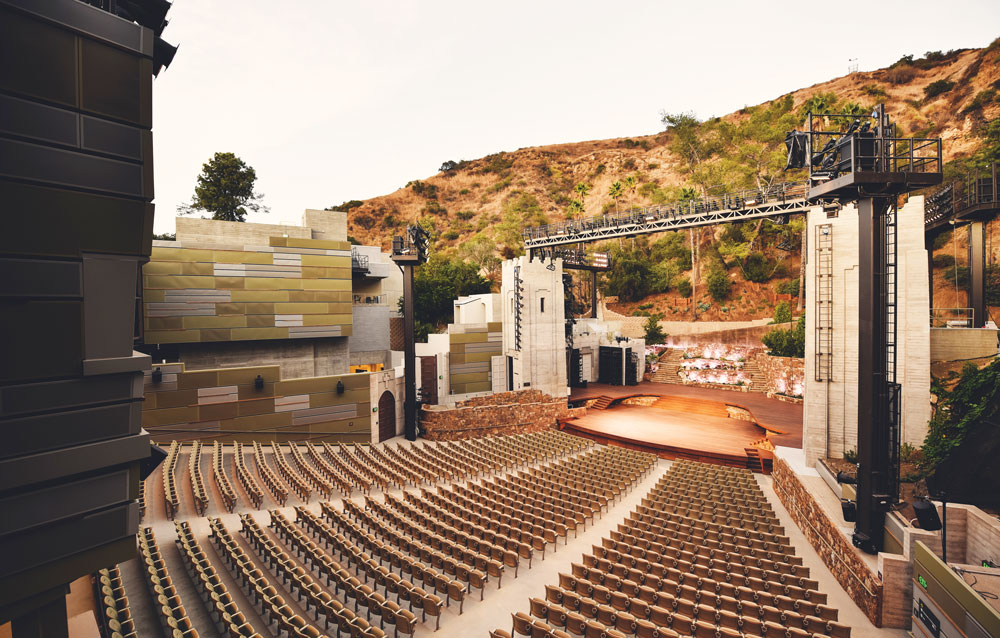
October 2017, renovated John Anson Ford Amphitheatre.
Tucked in a canyon in the Cahuenga Pass, the historic amphitheater is embedded in the steep slope of the hills around the site. Originally built as a wood framed structure in 1920 and destroyed by a brush fire in 1929, the Ford Amphitheatre was reconstructed out of reinforced concrete in 1931 (Figure 1). As the theatre structure aged, it became evident that improvements were needed. At the beginning of the renovation project, the team spent many hours on site trying to understand how the existing building structure fit within the site topography. The first challenge was understanding the existing building layout and structure since no original structural drawings were available. The lack of existing drawings meant the steel reinforcing in the concrete elements remained a mystery. The analysis of all existing concrete structural elements was a challenge throughout the project.
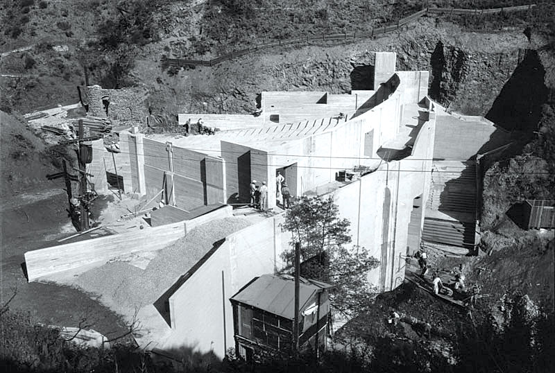
Figure 1. The theater reconstruction out of reinforced concrete (1931). Courtesy of the Los Angeles Public Library Photo Collection.
The canyon hillside is the backdrop for the amphitheater stage where a series of stepped stone retaining walls behind the stage were failing. It became clear that rebuilding the retaining walls was necessary. A significant amount of time was spent working with the contractor to come up with a design and layout that could be built on the hillside, as the retaining walls needed to step down towards the stage following the steep slope of the canyon. Coordinating access to transport construction materials and heavy machinery required outside-the-box thinking. The final solution used a large crane to lift construction materials and machinery from the staging area over the existing concrete stage tower onto the canyon hillside where the retaining walls were being constructed (Figure 2).
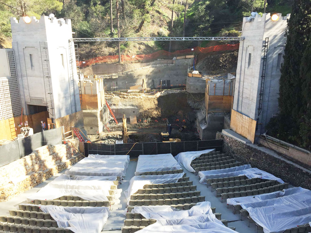
Figure 2. Construction of new stepped retaining walls behind the stage. Courtesy of Levin & Associates Architects.
The original stage was not centered on the amphitheater seating area. The design team was tasked with rebuilding a new stage that was centered and could house a lift connecting the split-level stage. Also, a portion of the subterranean area below the original stage was not usable due to the sloping canyon hillside that tucked under the stage slab. By reconstructing the stage, additional square footage was captured below. This created new back-of-house space for the performers. The new reinforced concrete stage was constructed with concrete retaining walls around the perimeter (Figure 3). The new stage retaining walls resist surcharge loads from the existing stage-left and stage-right towers and the newly constructed hillside retaining walls. Several potholes were dug adjacent to the existing structure to discover the size and depth of existing footings to determine the surcharge loading from the structure.
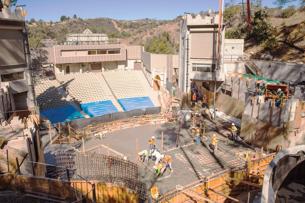
Figure 3. Construction of the new reinforced concrete stage. Courtesy of Levin & Associates Architects.
To improve the experience of both performers and audiences, the team also designed a new sound wall and control booth behind the amphitheater, along with multiple new lighting towers located on either side of the stage and the seating area (Figure 4). The twenty-five-foot tall sound wall improved the acoustics of the venue and shielded the theater from Hollywood Freeway noise. Early in the design process, the decision was made to work with a design/build contractor to design the aluminum sound wall. By using aluminum, the weight of the sound wall was reduced significantly. However, the large wall area and narrow depth created substantial overturning forces due to wind and seismic loads. Structural Focus designed a new structural steel support system for the sound wall while coordinating with the Texas-based design-build engineer. The new frames support the sound wall over the existing twelve-foot-tall historic concrete wall behind the seating area. Support columns penetrate through the amphitheater concrete slab and extend into the space below. Locations of the new sound wall support columns above and below the amphitheater were coordinated to avoid disrupting the existing concrete framing below. Without original building drawings and with a limited exploratory investigation, assumptions were made about the layout of the existing building foundations during the design phase. This led to more coordination and modifications during construction.
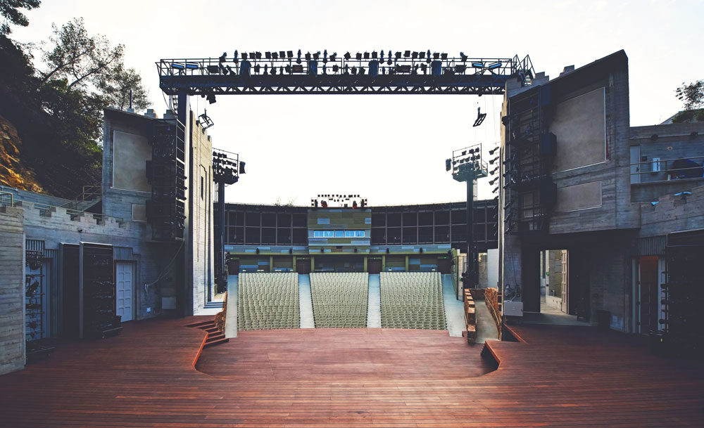
Figure 4. New sound wall and control booth behind the amphitheater.
There were several complexities associated with the design of the new lighting towers. In addition to catwalk lighting towers on either side of the new stage, cantilevered lighting towers were added on the right and the left side of the amphitheater seating area (Figure 4). The forty-five-foot-tall towers added significant foundation reactions to the complex hillside foundation system. The house-left tower required the construction of a new retaining wall below the amphitheater to resist surcharge loads.
A new proscenium truss spans sixty-five feet over the stage between the two existing concrete towers on either side (Figure 4). It is used to support lighting fixtures, banners, two 3,000-pound speakers (one at each end), and other theatrical equipment. The truss is supported on new HSS 20×20 columns connected to the towers for lateral support. Locating the new supporting columns adjacent and inside the existing concrete towers required coordination with the design team to limit the impact on the interior space of the towers and the historic characteristics of the amphitheater.
The new Ford Terrace building is tucked into the canyon hillside and constructed on the north side of the amphitheater with a seismic joint between the existing historic building and the new structure (Figure 5). A new stair and elevator tower between the amphitheater and the new structure provides access to both buildings. The three-story building includes a loading dock at the bottom with direct access to the stage, a terrace with a concession stand at the second level, and office space at the third level. The roof houses mechanical units for both the amphitheater and the Ford Terrace building (Figure 5). A mechanical screen wraps around the roof to hide the equipment.
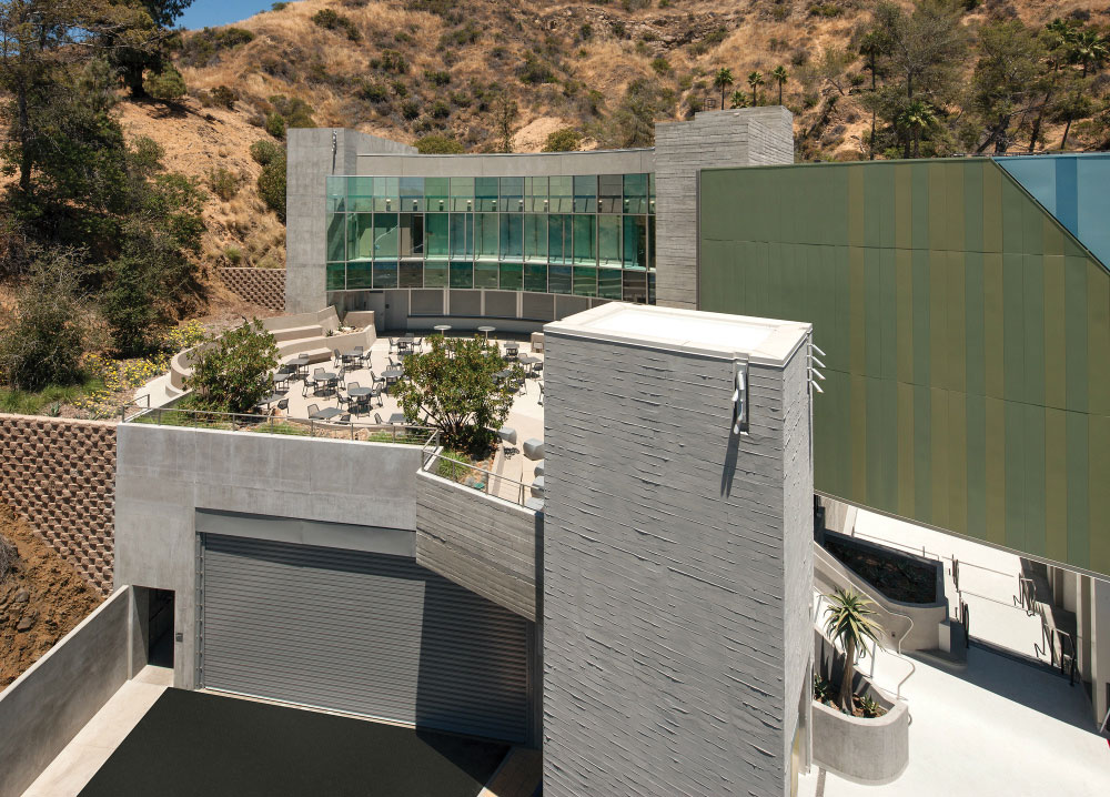
Figure 5. The new Ford Terrace building on the north side of the amphitheater. Courtesy of Tom Bonner Photography.
Similar to the new stage retaining walls, lateral soil pressure from the hillside was accounted for during the calculation of structural loads on the Ford Terrace building. The new building was designed to be structurally independent from the existing amphitheater, but there are several locations where the two buildings touch and isolation joints were required. This included a slide bearing joint at an exterior stair and a joint between adjacent retaining walls. The accelerated project schedule required careful coordination between the depth of the new building footings and the new stair and elevator tower to avoid shoring and surcharge loading on the amphitheater retaining walls. Also, vertical clearance requirements for truck access to the loading dock located below the terrace slab required that the location of the concrete columns that support the terrace slab, and the depth of the terrace slab beams, be limited and established very early in the design.
The existing and the new structures are also connected by a new underground tunnel between the area below the stage and the new building loading dock. Careful coordination with the contractor was required to build the tunnel because it passed under an existing historic wall that dictated shoring and protection during the excavation process. The new tunnel walls and lid were designed for the surcharge loads from the existing structure above.
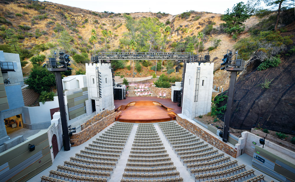
Figure 6. Renovated John Anson Ford Amphitheatre.
The team collaborated to solve challenging constraints and deliver a successful project. “We have had the pleasure of working with Brenda on several historic renovation and preservation projects,” stated Structural Focus Principal Russell Kehl, S.E. “Brenda is amazing at collaborating with her project team to solve challenging constraints and deliver a wonderful project that will be enjoyed by many generations to come.” In July 2017, the Ford re-opened as a state-of-the-art performance venue and cultural meeting place (Figure 6). In a recent interview with The Planning Report, Brenda Levin stated, “The Ford Theatres, for the first time in its 86-year history, has the capacity to be a competitor with any of the great venues in Los Angeles.”▪