
In addition to supporting gravity loads, floor and roof systems in typical reinforced concrete buildings act as diaphragms which transfer the lateral forces to shear walls, frames, or other elements that make up the lateral force resisting system (LFRS). A three-dimensional analysis that considers the relative rigidities of the diaphragm and the elements of the LFRS provides the most accurate distribution of the forces in these components. A more straightforward analysis is possible when assumptions are made concerning the rigidity of a diaphragm.
Cast-in-place, reinforced concrete slabs of typical proportions and span lengths can usually be considered rigid diaphragms, which means that the lateral forces are transferred to the elements of the LFRS in proportion to their relative rigidities. In systems that contain beams or ribs – like in wide-module, two-way joist and grillage systems – the elements below the slab help stiffen the diaphragm even further.
According to the American Concrete Institute’s ACI 318, Section 12.3, diaphragms must have sufficient thickness so that all applicable strength and serviceability requirements are satisfied. Usually, the thickness of a floor or roof system is determined first based on the strength and serviceability requirements pertaining to gravity loads. That thickness is typically sufficient to satisfy corresponding requirements for the combined factored load effects (gravity plus lateral) on the diaphragm.
In the case of gravity loads, many methods are available that can be used to determine the factored load effects, including the approximate methods in ACI 318 for one-way and two-way systems. For the most part, these methods are relatively simple to use and give very reasonable results. In contrast, the distribution of in-plane forces due to wind effects in diaphragms is complex. However, because a cast-in-place reinforced concrete system behaves more like a single, monolithic element compared to other types of systems, simplified analysis methods can be used to determine in-plane force distributions; these methods give results that compare well to those from more sophisticated procedures.
In-plane design bending moments, shear forces, and axial forces in a diaphragm are permitted to be calculated by the methods in ACI 318 Section 12.4.2.4:
- Rigid diaphragm model in cases where the diaphragm can be idealized as rigid;
- Flexible diaphragm model in cases where the diaphragm can be idealized as flexible;
- Bounding analysis, which considers results based on upper- and lower-bound in-plane stiffnesses of the diaphragm;
- Finite element model; and
- Strut-and-tie model in accordance with ACI 318 Section 23.2.
For reinforced concrete buildings with typical span lengths and without diaphragm irregularities (such as large openings or significant changes in diaphragm stiffness in adjoining stories), the rigid diaphragm model is commonly used to determine approximate force distributions within a diaphragm. In this method, a diaphragm is modeled as a horizontal rigid beam that is supported by springs which represent the lateral stiffness of the members in the LFRS. The roof and floor systems act as the web of the beam, which resists the design shear forces that are uniform through the depth of the diaphragm. The boundaries of the diaphragm act as the flanges which resist the flexural tension and compression design forces.
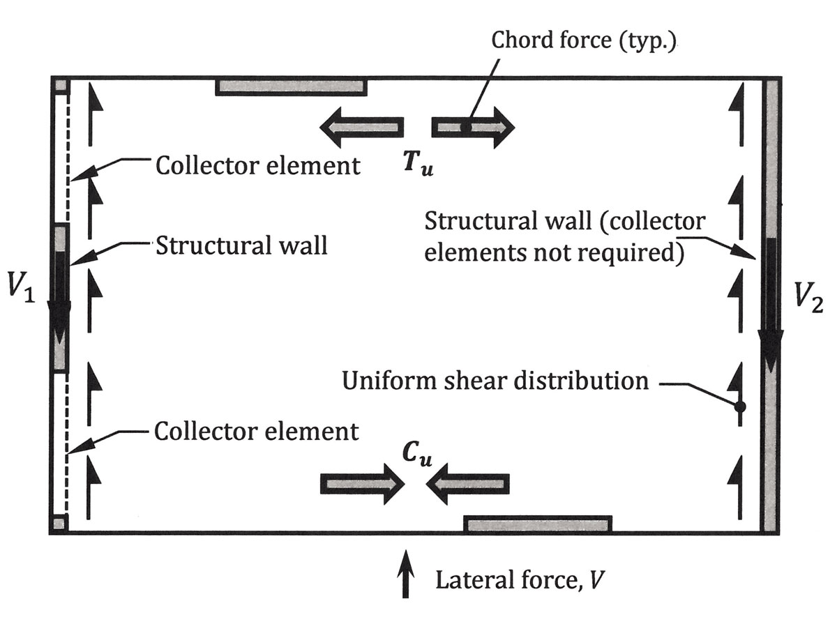
Figure 1. Diaphragm force distribution.
Illustrated in Figure 1 is a diaphragm with an LFRS consisting of structural walls and collector elements. The lateral force is transferred through the web of the diaphragm to the walls, which act as supports for the diaphragm. Because the wall on the left does not extend the full depth of the diaphragm, collector elements are needed to collect the shear from the diaphragm and to transfer it to the wall. The diaphragm boundaries that are perpendicular to the seismic lateral (commonly referred to as chords) resist the tension and compression flexural forces that are induced in the diaphragm. Boundary reinforcement is concentrated along the edges of the diaphragm to resist the tensile forces.
For diaphragms with openings, forces develop in the sub-diaphragms at the top and bottom of the opening and collector elements on each side of the opening are required to transfer the diaphragm shear into the sub-diaphragms (Figure 2).
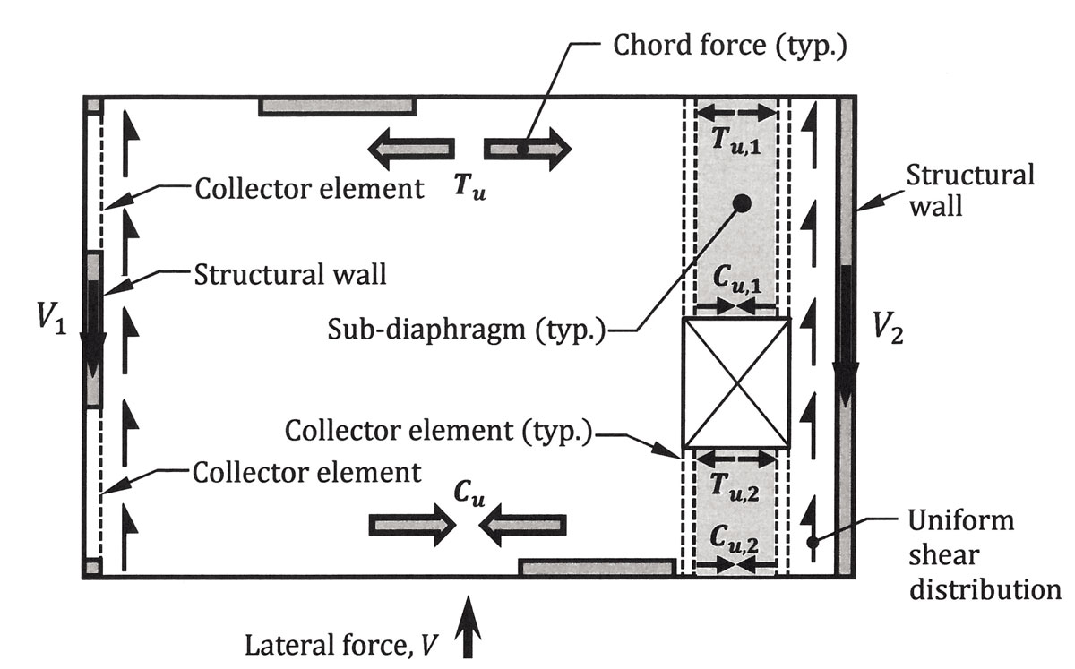
Figure 2. Force distribution in a diaphragm with an opening.
For buildings subjected to wind, it is assumed that the wind pressures acting over a tributary story height are uniformly distributed at that level over the width of the building that is perpendicular to the wind pressures. The resultant wind force acts through the geometric center of the building at that level.
In the usual case where the resultant wind force does not act through the center of rigidity (either due to geometry or minimum eccentricity requirements in the governing building code), a floor will translate and rotate. The members of the LFRS will be subjected to direct shear forces plus shear forces due to the torsional moment generated by the eccentricity.
An equivalent distributed load on the diaphragm can be obtained based on the reactions in the springs. The distributed load is trapezoidal, which is depicted in Figure 3 for a diaphragm without a significant opening. The loads w1 and w2 at each end can be obtained by using the equations for force equilibrium and moment equilibrium, and then solving these two equations for the two unknowns w1 and w2: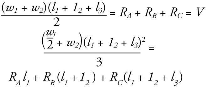
Once w1 and w2 have been determined, shear and moment diagrams can be obtained (Figure 3). The moment diagram is used in determining the required chord reinforcement near the edges of the diaphragm. The compression and tension forces in the chords caused by flexure due to the wind forces can be obtained from the following equation: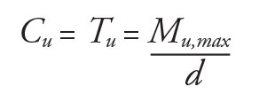
where d is the perpendicular distance between the chord forces, which is commonly taken as 95 percent of the total depth of the diaphragm in the direction of analysis.
Tension forces govern, so the required area of chord reinforcement, As, can be determined from the following equation: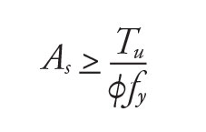
where φ = 0.9. Chord reinforcement must be provided in addition to any other required reinforcement, such as flexural reinforcement. In the case of roof and floor systems without perimeter beams, the chord reinforcing bars are typically concentrated near the edge of the slab and are tied to either the top or bottom flexural reinforcement. Chord reinforcement must also be located around large openings and must be properly developed within the slab.
The shear diagram is used in (1) checking the design shear strength of the diaphragm, (2) designing the connections of the diaphragm to the vertical elements of the LFRS, and (3) determining the axial compressive and tensile forces in any collectors.
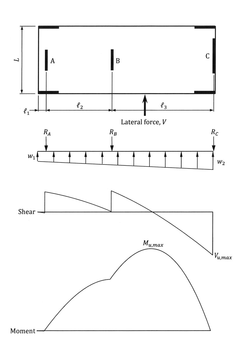
Figure 3. Rigid diaphragm model.
The in-plane shear force per unit length is assumed to be uniform along the depth of the diaphragm when the rigid diaphragm method of analysis is used. Referring to the diaphragm in Figure 3, the maximum in-plane shear force per unit length, in this case, occurs along the right side of the diaphragm and is equal to Vu,max/L, which must be less than or equal to the in-plane design shear strength per unit length given by ACI 318 Equation (12.5.3.3):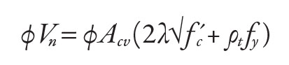
In this equation, Acv is equal to the gross area of the diaphragm (thickness times a one-foot unit length) and ρt is the distributed reinforcement in the diaphragm that is oriented in the direction of analysis (that is, parallel to the in-plane shear). It is conservative to assume that ρt is equal to zero when calculating φVn. Even when this conservative approach is used, shear strength requirements are commonly satisfied.
As noted previously, one of the primary roles of a diaphragm is to transfer wind forces to the elements of the LFRS. In typical cast-in-place reinforced concrete construction, this is accomplished by shear transfer reinforcement, which usually consists of dowel bars.

Figure 4. Determination of dowel reinforcement in a diaphragm.
Consider the diaphragm in Figure 4. Adjacent to wall B, the uniform shear force in the diaphragm is equal to RB/L, which is the same unit shear force in the wall. The strength requirement for shear transfer between the diaphragm and wall B is: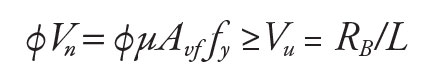
where φ = 0.75 and Vn is determined in accordance with the shear-friction provisions of ACI 318 Section 22.9.4.2. The coefficient of friction, μ, depends on the contact surface condition of the concrete, and Avf is the area of reinforcement that crosses the shear plane, which in this case is a construction joint. The following equation can be used to determine the required area of the dowel bars Avf for shear transfer: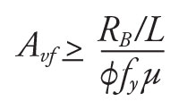
For hardened concrete that is clean, free of laitance, and not intentionally roughened, μ = 0.6 for normalweight concrete in the typical case where the slab and wall are cast at different times.
The shear transfer between the diaphragm and wall A in Figure 4 depends on the width of the collector elements. Where the width of the collectors is equal to the thickness of the wall, all the tension and compression forces from the collector are transferred directly into the boundary of the wall, and Avf is determined using the above equation based on the uniform shear along the length of the wall (which is equal to RA/L2). If the collector elements are wider than the wall, Avf must be determined using the uniform shear along the wall length plus a portion of the total collector force.
For shear transfer between the diaphragm and the collector elements at wall A, using μ = 1.4 to determine Avf is warranted because the diaphragm and collectors are usually cast monolithically.
The dowel reinforcement must be fully developed for tension into the wall and the diaphragm (see Section 1-1 in Figure 4). The reinforcing bars must extend at least the tension development length, ld, determined in accordance with ACI 318 Section 25.4.2, past the inside face of the wall and past the underside of the slab. The dowel bars must also be designed for any out-of-plane wind forces that act on the wall.
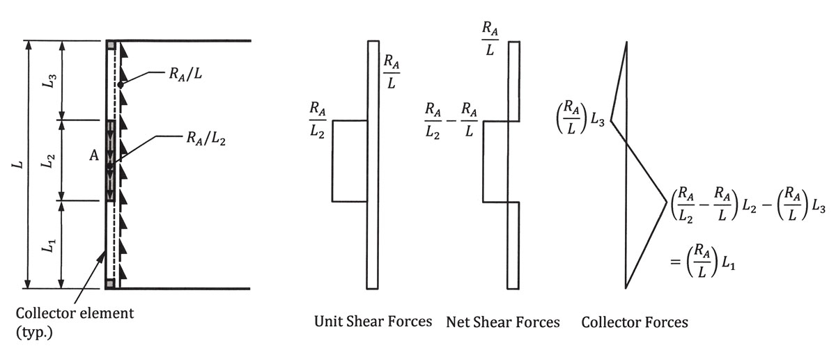
Figure 5. Unit shear forces, net shear forces, and collector forces in a diaphragm.
The axial forces in the collector elements at wall A in Figure 4 are determined by summing the areas in the net shear force diagram given in Figure 5. The collectors must be designed for this factored axial force (tension and compression) and any factored gravity loads tributary to the collector.
Additional information on the design and detailing of reinforced concrete diaphragms and collectors can be found in the CRSI publication Design and Detailing of Low-Rise Reinforced Concrete Buildings.▪
References
ACI (American Concrete Institute). 2014. Building Code Requirements for Structural Concrete and Commentary. ACI 318-14, Farmington Hills, Michigan.
CRSI (Concrete Reinforcing Steel Institute). 2017. Design and Detailing of Low-Rise Reinforced Concrete Buildings. Schaumburg, IL.