
20 Times Square, or 701 Seventh Avenue, is located on the northeast corner where 47th Street and Seventh Avenue intersect in New York City. When finished, 20 Times Square will host a variety of functions, including nearly 75,000 square feet of premium retail space and 30,000 square feet of multi-function entertainment spaces, with a premier nightclub and a 7,000 square foot rooftop terrace that overlooks the heart of Times Square. Nestled between the retail space and rooftop is a 150,000 square foot high-end hotel with 452 guest rooms (to be branded as a Marriott Edition, the collaboration between Ian Schrager and Marriott Hotels) and an 18,000 square foot hi-definition LED sign, rising 120 feet above the bustling streets below and wrapping around both the 47th Street and Seventh Avenue facades.
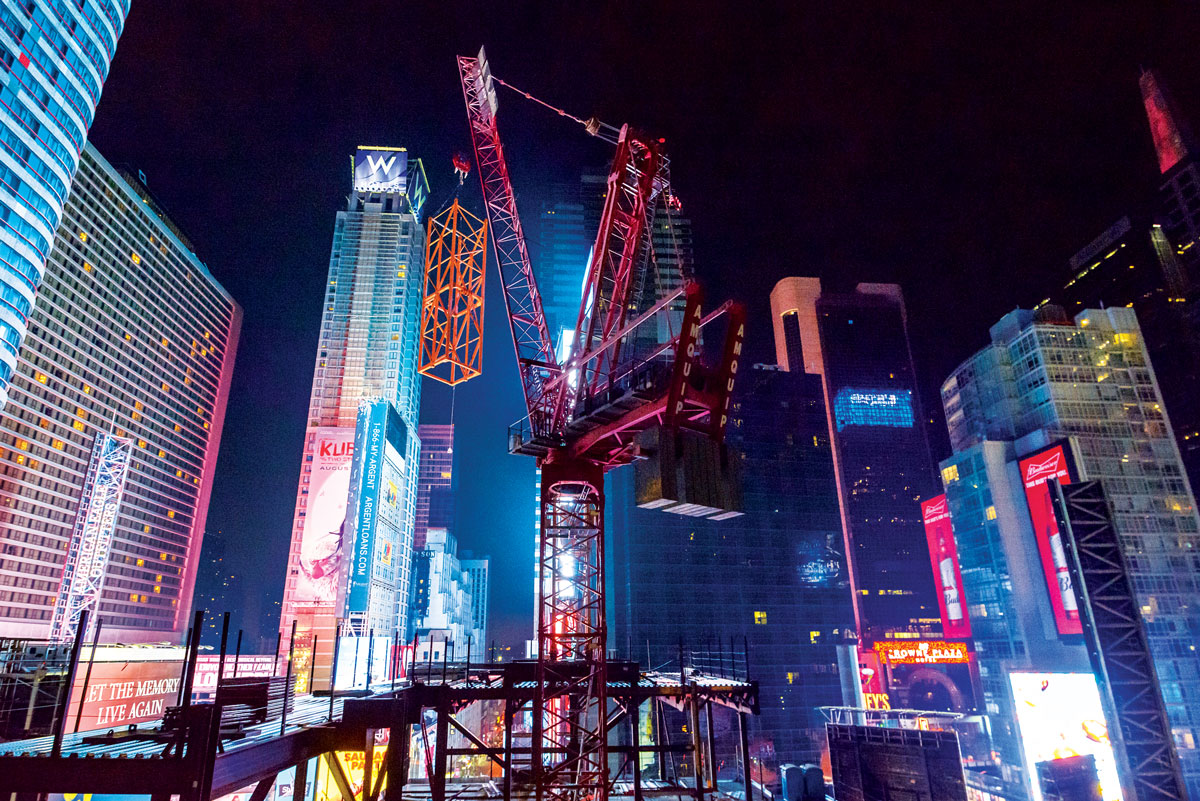
Night construction. Courtesy of Ralph D’Angelo.
In its finished state, the structure will encompass 378,000 square feet of floor space, rise 550 feet above the street, and have used 2,000 tons of Structural Steel and 21,400 cubic yards of reinforced cast-in-place concrete.
The Challenges
Building a 500-foot-tall tower at one of the busiest pedestrian intersections in the world is an undertaking, to say the least. Additionally, the site is approximately 150 feet east-west by 100 feet north-south, so the design needed to be compact and the floors had to support temporary construction loads, which often dwarf the service design live loads. However, the most significant design challenge was imposed by the programming of the building and the New York City zoning codes.
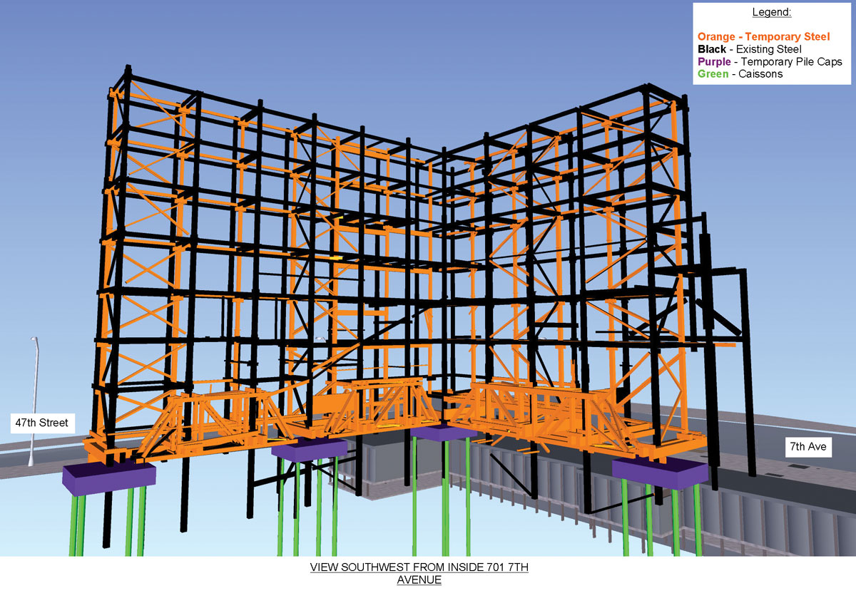
BIM model of the existing structure and temporary support structure. Courtesy of CNY.
The structure at the base of the tower, or the podium, houses premier and very valuable retail space, so high ceilings and open, column-free volumes were desirable. However, the bulk of the tower is comprised of hotel space, so a thin structural profile was necessary to optimize the number of floors within the prescribed height of the tower, a height which is capped by the New York City zoning code. Since a thin structural floor plate was desirable to optimize the volume of the hotel, columns and walls were needed to thin out the structural profile from floor to floor. However, the zoning code of Manhattan imposed yet another design constraint (the most impactful one of them all) – to maintain the existing building street-wall height of approximately 100 feet versus having a setback at 60 feet height and thus a street wall of 60 feet height, the construction of the building would have to qualify under an alteration permit. To comply, one of three criteria needed to be met:
- keep the existing foundations,
- keep a minimum of 50% of the existing façade, or
- keep a minimum of one-quarter (25%) of the structural floor levels of the existing buildings.
Under an alteration permit, the height of the existing street-wall could remain, and the existing floor level area would be integrated into the podium of the building. That would support the development of an 18,000-square foot wrap-around LED sign. To further compound the issue, there was insufficient documentation available for the existing structures.
The Existing Structure
The existing structural system of 701 Seventh Avenue, built in 1910, was comprised of a structural steel frame, cinder concrete flat arch floors, and non-bearing masonry walls. The footprint of the building originally formed an “L” along 7th Avenue and 47th Street and rose up 10 stories above the street, topping out around 150 feet in height. This type of construction was revolutionary to that era, as most structures up to that point utilized masonry walls on the exterior as load bearing vertical elements. Very limited documentation was available for both the structural and architectural aspects of the existing structure.
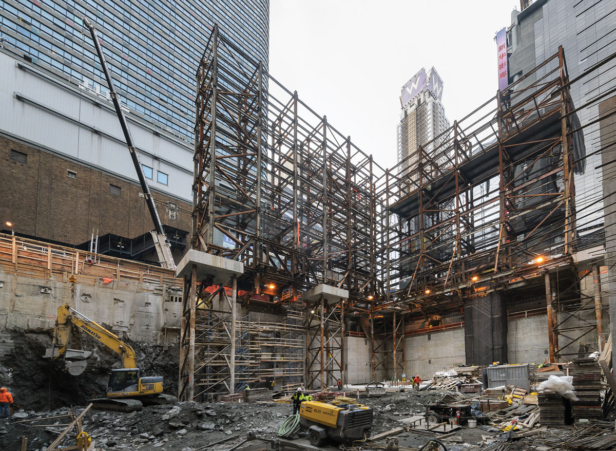
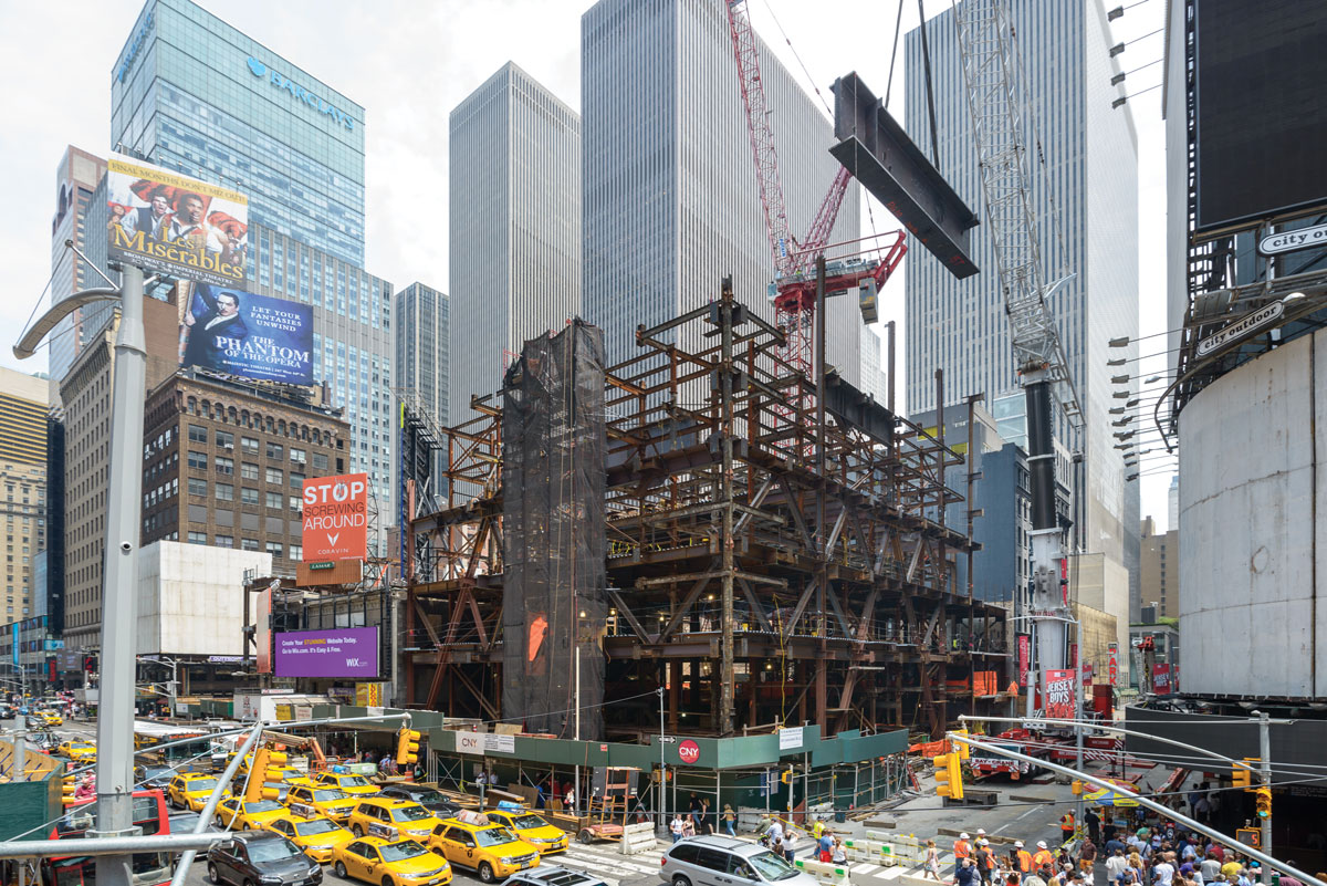
An as-built photograph of the existing structure and temporary support structure. Courtesy of Ralph D’Angelo.
To further complicate retaining 25% of the existing structure, a very intricate bracing system was introduced (designed by Howard Shapiro and Associates) to open key areas of the site to excavation crews while maintaining the stability of the existing structure that was to remain. This temporary bracing system was comprised of two forty-foot-long Pratt Trusses above the ground floor, caisson supported mast towers (which were extended along with the excavation), elevated caisson caps, braced frames, shoring columns, and shoring header beams. Unknown existing structural conditions warranted full-time site supervision by Howard Shapiro and Associates during installation of the temporary bracing and stability systems.
Due to the limited documentation, a three-dimensional laser scan survey was conducted on the architectural shell early in the project and of the existing structure later as the project developed. Additionally, the temporary bracing structure was installed to suit the multitude of different field conditions, which arose during inception. Thus, the laser scan also served as a three-dimensional as-built rendering of the temporary bracing and stability structure. Once the existing and temporary bracing structures were modeled as three-dimensional masses, utilizing point cloud data obtained by the laser scan survey, the new structure was coordinated and designed to avoid conflicts with both the existing structure to remain and the temporary structure. This coordination effort ultimately eased the installation of the new structural framing, saving the construction team and owner crucial time and money.
Site surveying was also conducted by the construction manager and the structural steel erector to verify the information obtained by the three-dimensional laser scan survey and to better pinpoint the detailing requirements associated with integrating and re-supporting the existing structural steel frame with the new structural steel. Having this very detailed survey information not only tightened the coordination and design of the new structure but also helped the structural steel fabricator and Engineer of Record, Severud Associates, detail connections between the new and existing structural steel frames.
The Transfer Solution
A retail base podium, which favors very long, deep, open structural spans, had to be fused with a hotel tower, which favors a very shallow structural profile. Further, the base podium needed to be designed and detailed around the existing building structure and the concrete tower was scheduled to host a variety of multi-functional volumes. Achieving these program constraints with one building material or structural system was not possible, so an elegantly designed structural transfer was required. A sturdy structural base had to support a heavy and compact tower.
The hotel tower, a structure composed of a cast-in-place concrete flat plate system, fifteen columns (spaced roughly 25 feet on-center), two shear wall cores, and a lot-line shear wall, needed to be transferred onto a steel frame which maintained an open floor plan by spanning fifty-plus feet between columns. A well-positioned mechanical level served as the dividing line between the hotel and the retail spaces; nestled in this vast space of mechanical equipment, the transfer structure that supports the hotel tower was proposed. Thirty-five plate girders, ranging in depth from 36 inches to 120 inches, transfer the concrete columns, the largest of which was a ten-foot-deep by three-foot-wide element weighing more than 120,000 pounds.
Fortunately, the lot-line shear wall transfers directly onto a structural steel braced frame below, and one of the shear wall cores spanned from foundation to roof. However, the main hotel elevator core, comprised of two, C-shaped shear walls, transfers to create a vast open retail space below. Two parallel 60-ton Transfer Trusses accomplish the Hotel Core Transfer and deliver the gravity load to four super columns each weighing about 1,200 pounds per linear foot. The lateral forces are transferred through reinforced 9th Floor and 7th Floor slabs that serve as diaphragms, and the combined system delivers all of the hotel tower’s forces to the structural steel system of the Retail-Entertainment Podium.
An Open Podium Structure
The optimal “White Box” retail and entertainment space requires large, open areas with the flexibility to run escalators and elevators, as well as stack merchandise, create unique experiences, entice consumers to enter the space, and make the experience commercially viable; revenue per square foot of floor area is the only driver.
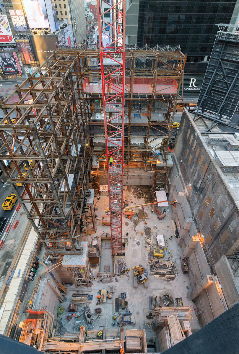
Overall view of the site at the completion of foundations. Courtesy of Ralph D’Angelo.
Columns are few and far between in the podium retail structure, due largely to the transfer structure on the 7th floor. Bracing is also scarce, but wind and seismic (lateral) forces are omnipresent; compounding the issue, the main lateral force resisting system of the hotel tower above ceases at the 7th floor. Stability had to be maintained by a minimally intrusive structural system, but large, built-up forces were present.
A megastructural steel “A” frame was introduced on both the 47th Street and 7th Avenue façades to stabilize not only the 120-foot podium structure but also the entire 400-foot-tall hotel and entertainment tower perched on top of the 7th-floor transfer structure. These two A-frames perfectly fit the programming of the retail space, since the perimeter of the building from the 3rd floor up is encapsulated by the wrap-around LED screen. Hence, exterior structural steel braces and columns stabilized the entire building structure. At the same time, the base of the podium between the street level and the 3rd floor offers prime store-front exposure to the thousands of passersby on Broadway and Seventh Avenue.
Once all forces reach the ground floor, a cast-in-place concrete foundation system, extending 50 feet below grade, collects and resists these forces. The base of the structural steel A-frame is integrated directly into the cast-in-place foundation system to ensure a direct and smooth force transfer.
Cohesive Structural Systems
The fusion of structural steel with cast-in-place concrete presents numerous challenges. Going from a cast-in-place concrete foundation to a structural steel podium, and then again to a cast-in-place concrete tower was a logistical challenge solved by creating a nuanced timeline where each trade operated independently of all other trades, and in its own separate vacuum.
While this system posed the most challenges to the design, logistics, and capital cost, it was the most efficient from a schedule perspective and saved a month when compared to other options. The trades were orchestrated to execute like opera performers on a two- and three-shift operation and included steel erected at night.
Given the carrying costs of over $170,000/day, schedule became the driving motivator in many aspects of the project. This meant installing the cast-in-place foundation system, the structural steel skeleton of the podium, the cast-in-place concrete podium floors, and, finally, the cast-in-place concrete system of the hotel tower in rapid linear progression. This process demanded rigorous attention to delivery dates from shop drawings through erection.
The process was accomplished by temporarily stabilizing the base of the building with structural steel braced frames located within the easterly cores of the podium and hotel structure. These braced frames allowed structural steel erection to seamlessly flow to completion, unimpeded by other trades. While structural steel was being erected, and the braced frame was being encapsulated in concrete, the cast-in-place concrete operations closely followed. Steel frames were minimalistic, designed to support just the amount of weight necessary until the composite system attained design strength and took command. Above the 7th-floor transfer structure, the cast-in-place concrete system continued while the composite concrete and steel structure below gained strength with each passing day.
Erecting a 10-foot-deep plate girder for the seventh level transfer system. Courtesy of Ralph D’Angelo.
A design limit of ten floors of concrete superstructure could not be exceeded without completing the concrete encasement below and the platform of plate girders. The construction (up and down) was coordinated to maximize the efficiency of the schedule.
The View from Up Top
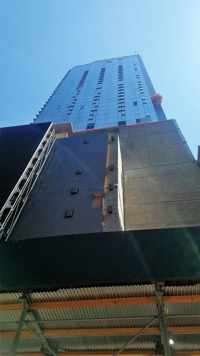
Topped out and clad.
No high-rise project is complete without a signature view and, when you are sited in Times Square, every vista needs to be optimally monetized. Walls and columns hinder this monetization. A column-free view was achieved by supporting the mechanical and roof structures above with concrete struts and ties. These outriggers cantilever off the elevator core of the hotel tower and hang the floor slabs of the two mechanical levels and the roof, thus eliminating all vertical structural elements along the west perimeter of the penthouse suite.
Although the view from the top hotel penthouse suite is indeed impressive, the hard work and dedication of the entire design, construction, and ownership team are evident throughout the project. Walking through the spaces, one realizes that everything is there because it needs to be there. There are no wasted gestures and flourishes, and systems integration is seamless. That level of design and construction only happens when a cohesive design-construct team, led by a dedicated owner, places the project’s needs above all others. 20 Times Square is greater than the sum of its parts.▪