
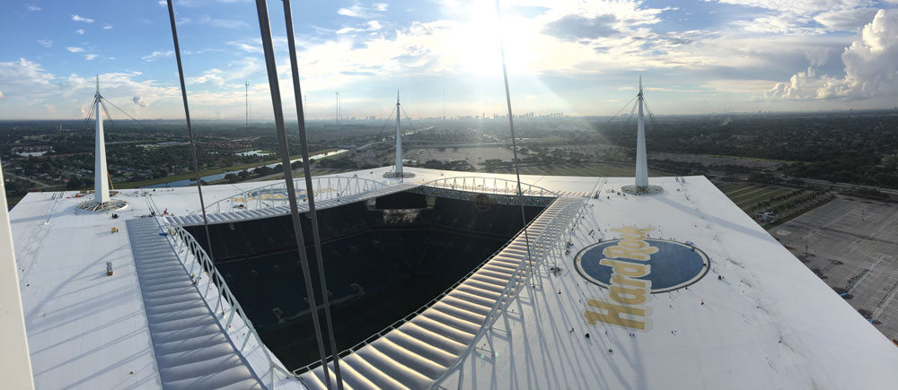
Shade Canopy
Erecting a 14-acre shade canopy, weighing more than 17,000 tons, over an existing NFL stadium in one offseason presented exceptional challenges to the Hard Rock Stadium project team. Hillsdale Fabricators of St. Louis, Missouri, assisted by erection engineers Ruby+Associates of Bingham Farms, Michigan, were up to the task. A complete transformation of the 30-year old stadium is highlighted by the beautiful new canopy, and the engineering behind its erection tells a unique story.
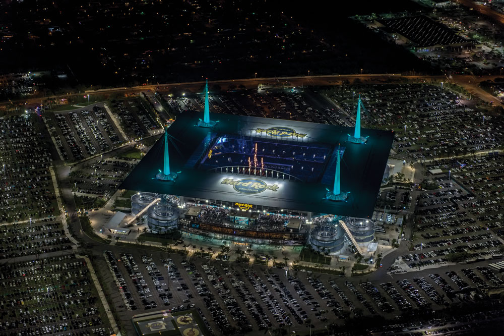
Courtesy of Miami Dolphins
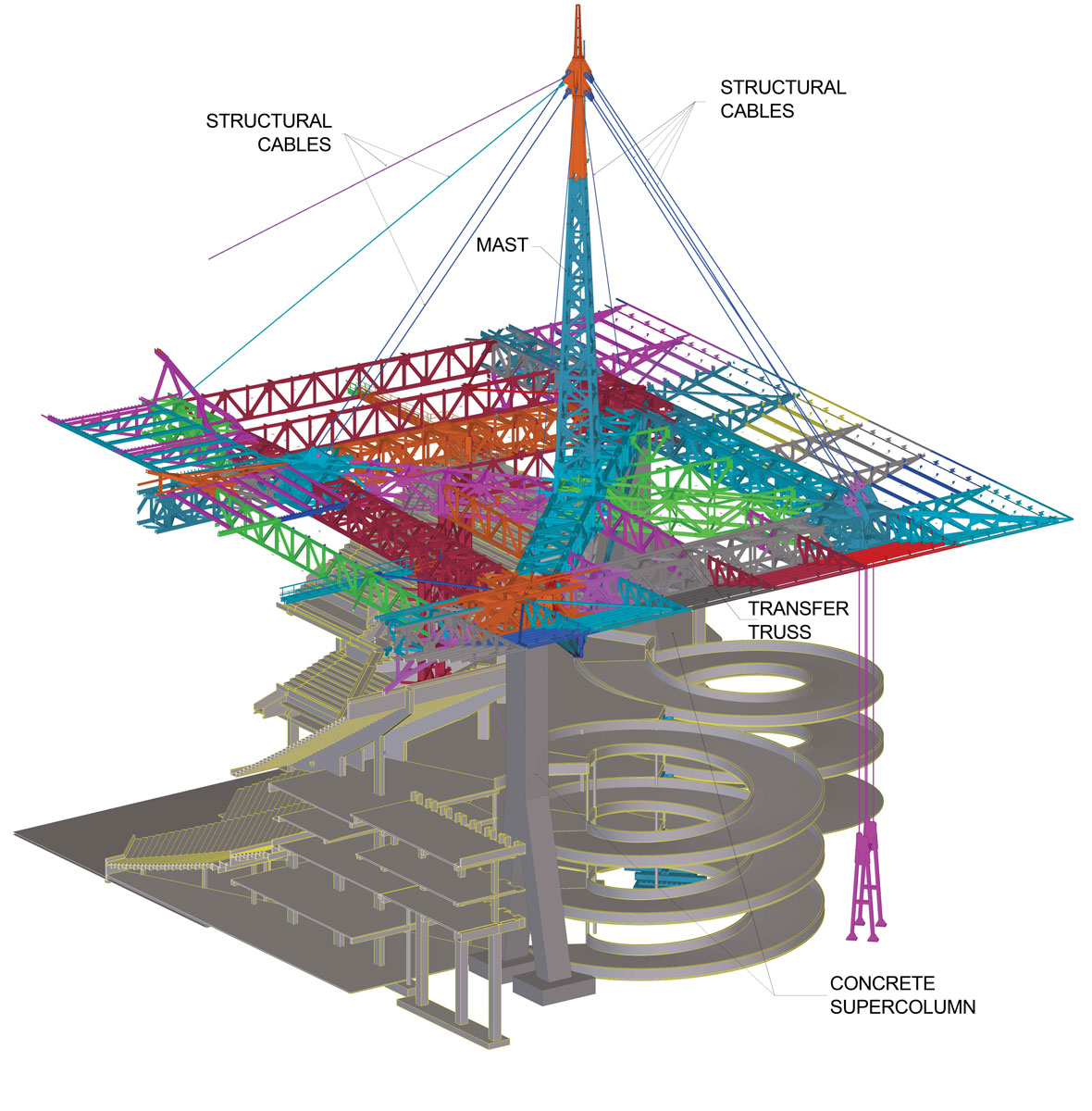
Designed by architect HOK and structural engineer Thornton Tomasetti, the structural steel canopy is part of a $500 million renovation of the 65,000-seat stadium. Upgrades include four massive, canopy-supported video boards, additional suites, and improved seating intended to appeal not only to Dolphins fans but also to the Super Bowl selection committee. The canopy provides shade over the stadium seating while leaving the area above the playing field open. Support is provided by a total of eight reinforced concrete super columns. At each corner, transfer trusses spanning between pairs of super columns support a 350-foot tall mast. Sixty-four locked coil steel cables, up to 300 feet in length, contribute to support of the canopy. This arrangement of structural elements provides redundancy in hurricane-prone Miami but also makes the canopy structure highly indeterminate, a feature that proved quite challenging when attempting to control the distribution of dead loads into the various structural members.
The Team
Ruby+Associates, Structural Engineers, provided full erection engineering services to fabricator/erector Hillsdale Fabricators. Redaelli Tecna S.P.A. of Milan, Italy, furnished the structural cable and fittings and assisted in their installation. Redaelli also provided significant cable expertise and important feedback on the design of the cable tensioning system. Terracon of Winter Park, Florida, performed geotechnical studies of the soil bearing capacity beneath the mobile cranes and temporary shoring. Esskay Structures of Tamilnadu, India, was retained by Hillsdale Fabricators to provide the fabrication details for the canopy and developed a 3D Tekla model that was used extensively in erection planning. Hillsdale Fabricators’ construction and engineering staff also provided vital input and coordination.
The “No Shoring” Alternate
One of the primary objectives in developing the erection plan was minimizing the impact of the canopy installation on the existing stadium below. Typically, a structure of this magnitude requires extensive shoring to provide temporary support during construction. The bid documents contained a suggested erection procedure that utilized 24 shoring towers. Not only would this shoring have been expensive and time-intensive to install, but it would also have required considerable repair to the finished stadium spaces after removal. An innovative steel erection plan was devised requiring minimal shoring and no alterations to the existing stadium to overcome these constraints.
Temporary tendons support balanced cantilevers.
One element of the erection scheme, borrowed from bridge construction techniques, was the use of balanced cantilevers. By sequencing construction such that loads imposed on the supporting structure stayed in balance, each corner of the structure could be erected in its entirety. To support this portion of the canopy until the permanent cables could be installed, temporary tendons consisting of W12x96 sections were positioned along the masts. The tendons permitted each of the corner areas of the canopy to be completed independently, allowing Hillsdale flexibility in erection sequencing as fabricated steel was delivered to the site.

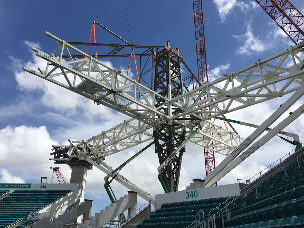
Four-crane lift using custom-designed lift frames.
Another method used to limit shoring, commonly employed in the power industry, is the subassembly of components into large, self-supporting sections. Hillsdale was very familiar with this method, having employed it successfully on numerous complex power plant projects. This concept was taken one step further for the stadium project by incorporating the two 450-foot outer sideline trusses and two 350-foot outer end zone box trusses into four enormous lifts. Two custom-designed lifting frames, each weighing only 35,000 pounds but capable of safely lifting 350 tons, ensured loads were equally shared by the four massive cranes used to perform each lift. The erection scheme also utilized the locked coil steel cables, ranging in size from 3½ to 5 inches in diameter, for support of portions of the canopy structure during construction. Careful analysis was necessary to determine the erected geometry and to control construction loads in the structural members. During erection, portions of the structure were temporarily suspended in place by mobile cranes while the cables were attached in midair. The canopy assemblies were installed in a super-elevated position, allowing the canopy weight to tension the cables and deflect the canopy into its final location. The cable tensioning system was designed to provide up to 1,200,000 pounds of pretension in case the cables required re-tensioning after most of the canopy load was in place. The erection sequence was specifically designed to limit most cables to a single tensioning action; however, for some cables, a two-stage tensioning process was required to maintain geometric alignment and prevent undesired dead loads in certain members. During the second tensioning, the sideline cables were loaded to 924,000 pounds tension. The cable tensions and structural deformations predicted in modeling were sufficiently accurate that no cables required further tensioning to meet project loading and alignment parameters.
Software Proves Critical
3D modeling was used in nearly every facet of erection planning, including structural analysis, modeling the behavior of the structural cables, performing clearance studies, developing rigging and erection plans, and determining crane placements.
Partial Tekla model.
The distribution of loads and the overall deformation of a highly indeterminate structure like the Hard Rock Stadium Shade Canopy was dependent on the varying stiffness of the many structural components during the erection process. Although it expedited steel erection, the elimination of shoring increased the complexity of the analysis significantly. The erection procedure had to take into account the deformation of the structural members and support cables at each stage of erection to ensure that the prefabricated and sub assembled components would fit together and that the geometry of the completed structure was within acceptable tolerances. Cable lengths and pre-tensioning requirements, erected geometry, as well as member construction loads and deformations, were determined using SAP2000 modeling software. The SAP model contained 52 separate construction stages, with the deformation and member forces of each sequence influencing the deformation and member forces of the subsequent sequence.
A detailed 3D model of the shade canopy was developed during fabrication detailing using Tekla Structures. Portions of the overall model were extracted to capture the erection subassemblies. From these extracted subassemblies, the exact weight and center of gravity of lifted components were determined and rigging locations identified. The extracted Tekla models were then imported to RISA 3D to determine rigging loads and to confirm that construction loads did not exceed member capacities. The Tekla model was also used to check installation clearances and to determine which splice plates to attach on the ground and which to install in the air. Also, Tekla was used to produce the rigging lift arrangement drawings.
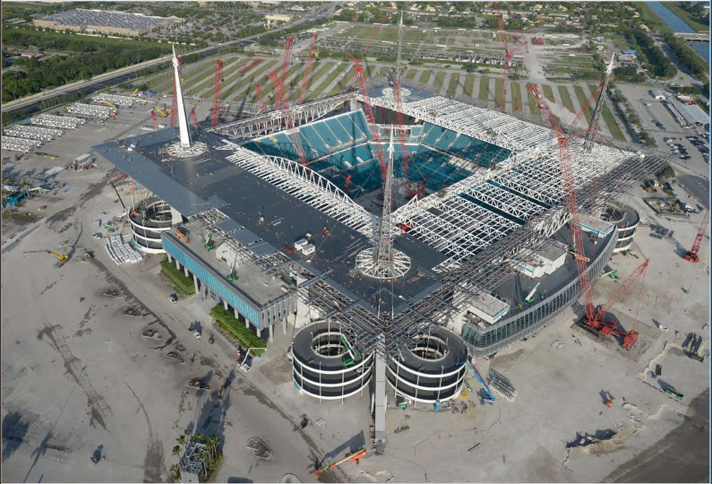
Seven cranes were used to erect the canopy.
The Tekla model was also employed to perform crane clearance studies and to determine the placement of the construction cranes. To-scale 3D models of the cranes were imported into the Tekla model, and crane positions were adjusted when a clearance study determined they were too close to the existing structure.
Complex & Challenging
It took the combined skills of the construction and engineering team, borrowing diverse techniques from both bridge building and heavy industrial construction, to safely and successfully complete the Hard Rock Stadium canopy in time for the first 2016 NFL preseason game. In mid-2016, with canopy construction well underway, Hard Rock Stadium was selected to host Super Bowl LIV, to be played in 2020.
Completed canopy.
As structures increase in complexity, new and adapted techniques will be required to facilitate their construction. This project is an excellent example of the need for innovation and advanced analytical procedures in meeting the demands of current and future building design.▪