
Utilizing Force Transfer Around Openings
The lateral force-resisting system tends to be one of the most challenging aspects of the structural design of a building. In today’s wood-framed construction, designers consistently see larger buildings combined with bigger and more numerous window and door openings. This construction trend usually translates into reduced areas for lateral resistance throughout the structure.
There are several ways to address this challenge. The American Wood Council (AWC) publication, Special Design Provisions for Wind & Seismic (SDPWS), provides designers three acceptable methods for designing wood shear walls to resist lateral forces: 1) Individual Full-Height Wall Segments, the “traditional” design approach; 2) Perforated Shear Walls, an empirical design method based on the percentage of full-height wall segments adjacent to openings; and 3) Force Transfer Shear Walls, referred to in this article as force transfer around openings (FTAO), allows the utilization of the full wall geometry, including sheathed areas above and below openings.
Historically, the FTAO method has been considered a last resort in the design industry, due in large part to the fact that it is more comprehensive and therefore assumed to be more time-consuming than the other two design options. The application of the FTAO method also varies greatly within the industry, as the code merely states that the design must be based on rational analysis. With no clear directive in the design codes, there have been multiple design rationale techniques developed (e.g., Drag-Strut Analogy, Cantilever Beam, Diekmann), which has caused some dispute between design professionals as to which technique is the most precise. These discrepancies are what led APA to perform full-scale wall tests on the FTAO design methodology, intended to prove that the application of FTAO can be more practical and simultaneously provide the most design flexibility.
This article discusses the benefits of FTAO for wood-framed structures, illustrates the testing performed on wood structural panel sheathed wood-framed shear walls for the enhancement of FTAO methodology, and provides a design example for a wood-framed shear wall with multiple openings and asymmetric wall piers.
Benefits of FTAO Wood Shear Walls
There are many benefits to the FTAO method, such as utilizing the entire shear wall geometry to resist the applied load, potentially reducing the number of hold-downs, and reducing the base plate shear anchorage. However, the most significant benefit of FTAO over other shear wall design methods lies within the definition of the wall pier aspect ratio.
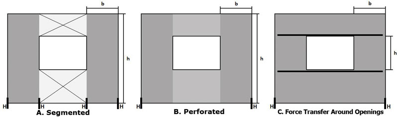
Figure 1. Illustration of aspect ratio (h/b) comparison for all three shear wall methods.
In the segmented and perforated methods, the aspect ratio of the contributing wall piers is defined as the full height of the wall system divided by the length of the wall pier (Figure 1a and 1b). When utilizing the FTAO method, the aspect ratio of the wall pier is defined as the height of the opening divided by the length of the adjacent wall pier (Figure 1c).
For example, given the wall illustrations in Figure 1 where the full height (h) is equal to 10 feet and the opening is 4 feet tall, the minimum wall pier length (b) allowed to be included in the design at the 2:1 aspect ratio for each method would be: segmented and perforated are equal to (10/2) or 5 feet and FTAO is equal to (4/2) or 2 feet. This benefit not only allows for narrower wall segments but also helps increase the overall height of the wall system where other methods might be limited.
This benefit is furthered by utilizing wood structural panel sheathing. The governing aspect ratio limitation in most applicable building codes for wood structural panels is 2:1, with a maximum of 3.5:1 (with the application of an adjustment factor). Although the use of other building materials is permitted, the aspect ratios either cannot exceed 2:1 or a load reduction factor is applied when the aspect ratio surpasses 1:1 per SDPWS Section 4.3.4.
Testing FTAO Design Methodology
FTAO has become more popular amongst design professionals as a viable shear wall analysis for wood-framed walls. The majority of the published FTAO design examples, however, are limited to the wall containing a single opening and, until recently, the recognized FTAO methods were tested in a limited number of installations.
In 2009, a joint research project was conducted by APA–The Engineered Wood Association (APA), the University of British Columbia (UBC), and the USDA Forest Products Laboratory to examine the internal forces generated in wood structural panel sheathed wood-framed shear walls during a lateral event. The test results, in conjunction with analytical computer-based models from UBC (twelve full-scale, 8-foot x 12-foot wall configurations) were used to develop an enhanced FTAO design methodology and evaluate the accuracy of the calculated forces in the walls using historic FTAO methods.
The initial testing determined the Diekmann rational analysis as the most accurate simplified method to estimate the forces in the shear wall. Using this approach as the basis, APA expanded the methodology to incorporate multiple openings and asymmetric piers. This methodology is based on the following key design assumptions:
- The unit shear is equivalent above and below the openings.
- The corner forces are based on the unit shear above and below the openings and only the wall piers adjacent to that unique opening.
- The tributary length of the opening is the basis for calculating the shear to each wall pier.
- The shear to each wall pier is the total shear divided by the length of the wall, multiplied by the sum of the pier length plus the tributary width of the adjacent openings, divided by the pier length: v1 = (V/L)*((L1 + T1)/L1) Equation 1
- The unit shear in the corner zones is equal to subtracting the corner forces from the panel resistance, R, which is equal to the shear of the pier multiplied by pier length:
Va1 = (v1L1–F1)/L1 Equation 2 - The design is checked by summing the shears along each vertical line. The first and last lines sum to the hold-down force and the interior lines sum to zero (Figure 2).
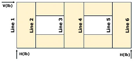
Figure 2. Vertical shear line illustration.
Testing data was also used to analyze the overall deflection of the FTAO wall systems, which verified that the sheathing below the openings aided in resisting the overall deflection of the wall. To attain the most accurate fastener deformation variable, the basis of the testing was completed using the four-term deflection equation, 2015 International Building Code (IBC) Equation 23-2: Δ = 8vh3/EAb + vh/Gt + 0.75hen + da h/b
Note that the 3-term deflection equation provided in SDPWS (Equation 4.3-1) may also be used, but the deflection calculations must be consistent throughout the design.
The wall deflection assumption (Figure 3) is that the total deflection of the FTAO shear wall is equivalent to the average of the deflection of each wall pier in both the positive and negative directions. The wall pier heights also vary depending on the deflection direction and amount of sheathing below the openings. For example, in Figure 3, positive deflection of wall pier 1 (δ1+) is determined using the height measured from the bottom of the opening to the top of the wall due to the resistance of the wall sheathing below the opening. Negative deflection of wall pier 1 (δ1-) is determined using the full wall height.
Δ = average (δ1+, δ2+, δ3+, δ1-, δ2-, δ3-) Equation 3
FTAO Design Example
Historically, FTAO design examples have been completed showing symmetric wall pier widths and a single opening in the wall system. Figure 4, illustrates the benefits of FTAO for walls with multiple openings and asymmetric wall pier widths.
Given a 20-foot-long wall that is 10 feet tall with a 4,000-pound shear force applied to the top of the wall, use the FTAO method to calculate hold-down forces, required strap forces, and required wall sheathing capacity.
Begin by calculating the hold-down forces at each end of the shear wall:
Step 1. H = (V*h)/L = ((4,000 lb)(10 ft))/(20 ft) = 2,000 pounds
The selected hold-downs must have a minimum capacity of 2,000 pounds.
Both the unit shear and boundary forces above and below the openings must be determined to attain the corner forces.
Step 2. Unit Shear Above and Below Openings:
va = vb = H/(ha + hb) = 2,000 lb/(2 ft + 3 ft) = 400 plf
Step 3. Total boundary force above and below the openings:
O1 = (va)(LO1) = (400 plf)(4 ft) = 1,600 pounds
O2 = (va)(LO2) = (400 plf)(6 ft) = 2,400 pounds
Calculate the corner forces at each opening to determine the maximum strap force required:
Step 4. F1 = ((O1)(L1))/(L1 + L2) = ((1,600 lb)(2 ft))/(2 ft + 4.5 ft) = 492 pounds
F2 = ((O1)(L2))/(L1 + L2) = ((1,600 lb)(4.5 ft))/(2 ft + 4.5 ft) = 1,108 pounds
F3 = ((O2)(L2))/(L2+L3) = ((2,400 lb)(4.5 ft))/(4.5 ft + 3.5 ft) = 1,350 pounds
F4 = ((O2)(L3))/(L2 + L3) = ((2,400 lb)(3.5 ft))/(4.5 ft + 3.5 ft) = 1,050 pounds
The selected strapping to be placed above and below the openings must have a minimum tension capacity of 1,350 pounds.
To calculate the unit shear beside the openings and to determine the wall sheathing requirement, the tributary width of each internal shear line must be determined.
Step 5. T1 = ((L1)(LO1))/(L1 + L2) = ((2 ft)(4 ft))/(2 ft + 4.5 ft) = 1.23 feet
T2 = ((L2)(LO1))/(L1 + L2) = ((4.5 ft)(4 ft))/(2 ft + 4.5 ft) = 2.77 feet
T3 = ((L2)(LO2))/(L2 + L3) = ((4.5 ft)(6 ft))/(4.5 ft + 3.5 ft ) = 3.38 feet
T4 = ((L3)(LO2))/(L2 + L3) = ((3.5 ft)(6 ft))/(4.5 ft + 3.5 ft ) = 2.63 feet
Using the tributary width to the internal shear lines, the maximum unit shear beside the openings can be calculated to determine the required wall sheathing capacity.
Step 6. V1 = ((V/L)(L1 + T1))/L1 = ((4,000 lb/20 ft)(2 ft + 1.23 ft))/(2 ft) = 323 plf
V2 = ((V/L)(T2 + L2 + T3)/L2 = ((4,000 lb/20 ft)(2.77 ft + 4.5 ft + 3.38 ft))/(4.5 ft) = 473 plf
V3 = ((V/L)(T4 + L3)/L3 = ((4,000 lb/20 ft)(2.63 ft + 3.5 ft))/(3.5 ft) = 350 plf
The selected wall sheathing must have a minimum shear capacity of 473 plf.
Note that, as a calculation verification, the sum of the unit shears multiplied by the length of the adjacent wall pier should be equal to the initial shear force:
(V1)(L1) + (V2)(L2) + (V3)(L3) = V
(323 plf)(2 ft) + (473 plf)(4.5 ft) + (350 plf)(3.5 ft) = 4,000 lb (This checks.)
The final design assumption must be met to verify the calculations. The sum of the shear-line forces at the outside lines must be equal to the hold-down force, and the sum of each interior shear line must be equal to zero. The corner force resistance and corner zone unit shears must be determined to perform this verification.
The corner force resistance, R, for each pier is determined by multiplying the unit shear in each wall pier by the corresponding wall pier length:
Step 7. R1 = (V1)(L1) = (323 plf)(2 ft) = 646 pounds
R2 = (V2)(L2)= (473 plf)(4.5 ft) = 2,129 pounds
R3 = (V3)(L3)= (350 plf)(3.5 ft) = 1,225 pounds
To calculate the corner force unit shear in each wall pier, the resultant shear force in the corner zone must be determined, then divided by the corresponding wall pier length:
Step 8. R1-F1 = 646 lb – 492 lb = 154 pounds
R2-F2-F3 = 2,129 lb – 1,108 lb – 1,350 lb = -329 pounds
R3-F4 = 1,225 lb – 1,050 lb = 175 pounds
Step 9. vc1 = (R1-F1)/L1 = (154 lb)/2 ft = 77 plf
vc2 = (R2 – F2 – F3)/L2= (-329 lb)/4.5 ft = -73 plf
vc3 = (R3 – F4)/L3 = (175 lb)/3.5 ft = 50 plf
Performing a design check by summing the forces at each shear line completes the analysis:
Step 10. Line 1: (va1)(ha + hb) + (V1)(ho) = H?
(77 plf)(2 ft + 3 ft) + (323 plf)(5 ft) = 2,000 lb
Line 2: (va)(ha + hb)–(va1)(ha + hb)–(V1)(ho) = 0?
(400 plf)(2 ft + 3 ft)–(77 plf)(2 ft + 3 ft)–(323 plf)(5 ft) = 0
Line 3: (va2)(ha + hb) + (V2)(ho)–(va)(ha + hb)= 0?
(-73 plf)(2 ft + 3 ft) + (473 plf)(5 ft)–(400 plf)(2 ft + 3 ft) = 0
Line 4 = Line 3
Line 5: (va)(ha + hb)–(va3)(ha + hb)–(V3)(ho)= 0?
(400 plf)(2 ft + 3 ft)–(50 plf)(2 ft + 3 ft)–(350 plf)(5 ft) = 0
Line 6: (va3)(ha + hb) + (V3)(ho) = H?
(50 plf)(2 ft + 3 ft) + (350 plf)(5 ft) = 2,000 lb
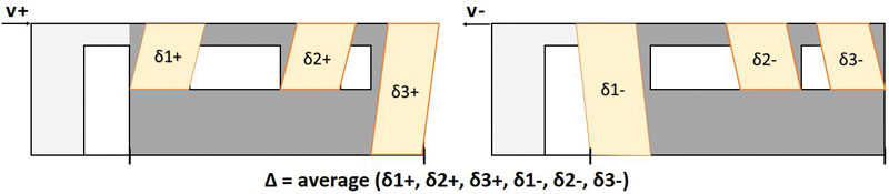
Figure 3. FTAO deflection illustration.
Using the 4-term deflection equation (Figure 3; Equation 3), overall wall deflection is calculated by determining the average of the positive and negative deflection values for each pier (Figure 4). Assuming a maximum hold-down capacity of 2,500 pounds, nail slip of 0.125 inches, and an APA Rated Sheathing 15⁄32-inch performance category with 8d nails at 4 inches on-center:
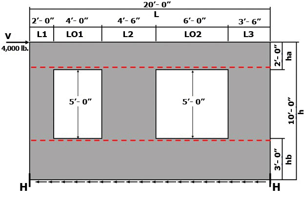
Figure 4. Design example illustration.
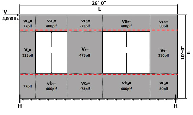
Figure 5. Wall force diagram illustration.
Step 11. Δ = average (δ1+, δ2+, δ3+,δ1, δ2-, δ3- = average (1.393,0.692,0.508,0.708,0.692,0.963) (in) = 0.826 inches
APA has automated the calculation process in the previous example with the creation of an FTAO spreadsheet (www.apawood.org/designerscircle-ftao). The spreadsheet is based on the tested methodology and provides engineers with the required hold-down forces, tension strap forces, and wall sheathing capacity. Finally, the tool automatically completes the design check in Step 9. The spreadsheet also provides shear wall deflection calculations for the 3- and 4-term deflection equation options.
Conclusion
With the introduction of a new method for estimating the overall wall deflection and tested verification for the accuracy of force transfer around openings (FTAO) shear walls, designers can be confident in having another valuable tool to apply when designing the lateral resisting system for wood buildings. The FTAO method helps expand the boundaries of building design with wood-framed walls, utilizing the full shear wall geometry to help increase the design flexibility and potentially reduce the economic impact of the lateral resisting system.▪