
Aerodynamic Evaluation and Retrofit Design
A comprehensive wind study of the Robert F. Kennedy Bridge suspended span was performed to determine if the bridge meets current aerodynamic criteria and ensure that it responds to wind events in a predictable manner. The suspended structure, an important facility in the New York Metropolitan area, features a 1,380-foot long main span, two 670-foot wide side spans and a minimum navigational vertical clearance of 150 feet (Figure 1). The bridge carries eight lanes of traffic in an eighty-seven-foot curb-to-curb width. The suspended structure is composed of two, 20-foot deep stiffening trusses connected to the main support cables and suspenders, and transverse floor beam trusses spaced at approximately twenty-eight feet on centers. In 2000, the original concrete decks and crossbeams were replaced with steel orthotropic decks.
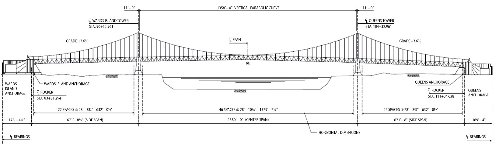
Figure 1. Suspended span. Courtesy of MTA Bridges and Tunnels.
Long-span bridges, such as the suspended spans of the RFK Bridge, need to be aerodynamically stable. The wind study tasks included analysis of wind climate, the establishment of equivalent static wind loads, sectional model testing, aerodynamic stability analysis, analysis of suspended spans for wind load, and retrofit design. The investigation also included the safety of wind-sensitive vehicles, such as trucks and buses, on the bridge during strong winds. These studies were performed for the RFK bridge by the Boundary Layer Wind Tunnel Laboratory (BLWTL) at the University of Western Ontario.
Design Criteria
Long span bridges need to be evaluated under wind loads for three limit states: serviceability, strength, and stability.
The serviceability limit relates to the usage of the bridge by passengers and can be expressed as deflection or accelerations. Normally, vertical accelerations in the range of 5%g to 10%g are considered acceptable for pedestrians. The maximum annual (1-year return period) wind speed is used for this evaluation.
The criteria for the strength limit are the same as those outlined in AASHTO’s LRFD Bridge Design Specification which is intended to ensure that the bridge has sufficient strength to resist the maximum wind loads during its design life. Load factors are used on the wind loads for checking of structural member capacities against yielding, buckling or shear failures. The maximum wind event for this limit state has a return period of 100 years.
The stability limit is a wind speed limit (flutter wind speed) above which the bridge will become unstable. Flutter is a self-excited instability caused by the interaction of the wind and the bridge structure involving either pure torsional motion or coupled vertical and torsional motion of a bridge deck. The instability can grow to very large amplitudes and lead to the collapse of the structure. The maximum wind speed for this limit state has a return period of 10,000 years.
Based on the wind climate study performed at BLWTL the criteria was recommended in Table 1 for the evaluation.
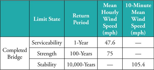
Table 1. Wind climate study evaluation criteria.
Section Model
A physical model of a typical cross section of the bridge was constructed at a geometric scale of 1:60 (Figure 2, page 33). The model was ballasted to the scaled mass properties and mounted on a dynamic test rig in which the fundamental vertical and torsional modal frequencies of the bridge deck were simulated. These properties were obtained from field vibration measurement and finite element modeling simulation. During testing, the bridge behaved satisfactorily under strong winds with regard to the Service and Strength limits. However, its flutter wind speed was only 88 mph, which does not meet the wind speed criteria for aerodynamic stability of 105.4 mph. The return period of 88 mph winds at the RFK Bridge site was approximately 1,000 years.
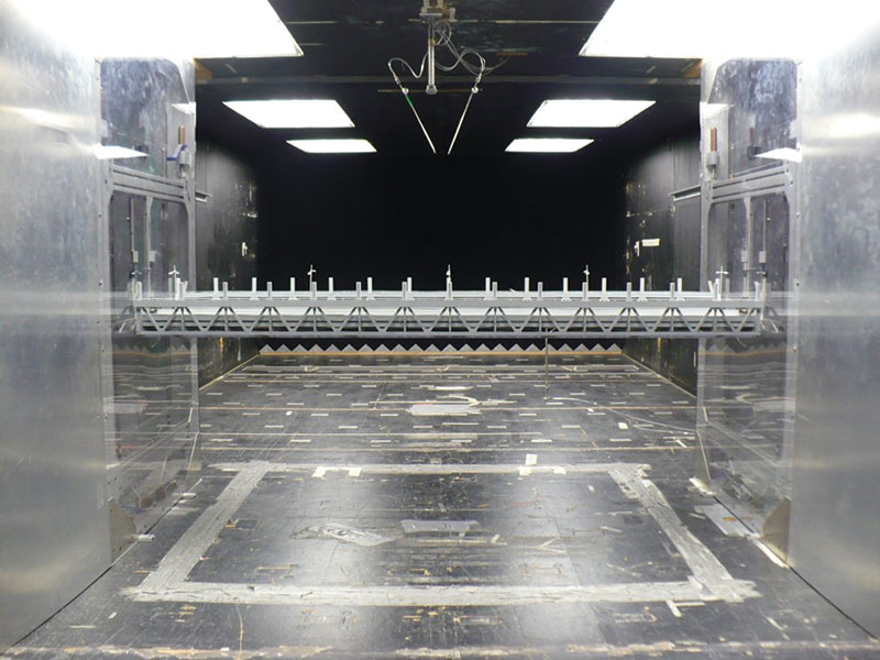
Figure 2. Wind section model of the RFK Bridge. Courtesy of Boundary Layer Wind Tunnel Laboratory.
Conceptual Retrofit Design
Given the low flutter wind speed for the main suspended span, it was apparent that making the bridge elevation more open to air flow was necessary to improve its aerodynamic performance. Conceptual design options for retrofit alternatives were developed that would improve the aerodynamic stability of the suspended spans. The effects of protective fencing were also included in this study.
The three retrofit alternatives developed were:
- Option 1: Replace existing solid roadway barriers with new open barriers (Figure 3)
- Option 2: Introduce perforations in the solid walkway fascia girders (Figure 4)
- Option 3: Replace existing solid walkway fascia girders with new shallower girder (Figure 5)
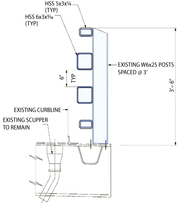
Figure 3. Retrofit open barrier.
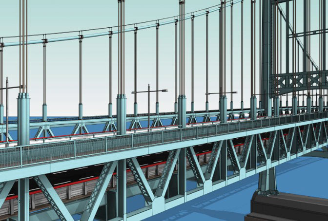
Figure 5. Shallow Fascia girder.
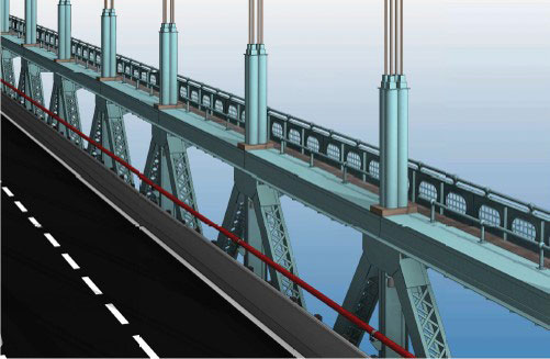
Figure 4. Perforations in sidewalk fascia girder.
Phase 1 Verification Testing
Phase 1 involved testing the wind retrofit alternatives and combinations of alternatives with protective fencing and selecting the alternative with best aerodynamic stabilities. Results are shown in Table 2.
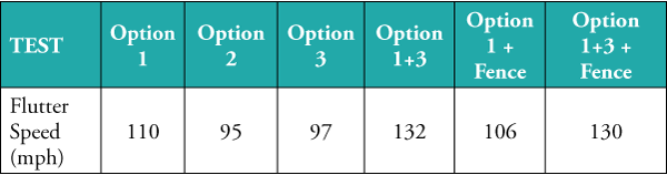
Table 2. Phase 1 test results.
On examination of the wind retrofits alternatives, the open barrier alone (Option 1) with no walkway or fencing modifications, the flutter criteria is satisfied. The combination of shallow fascia girder and open roadway barrier (Option 1+3) offers very significant improvements and increases the flutter speed to 132 mph, well above the 105.4 mph criterion. Protective fence components on both the roadway and sidewalk did not significantly reduce flutter wind speeds
A combination of Options 1 and 3 was recommended, together with protective fences on both walkway and roadway, as the final wind retrofit alternative (Figure 6).
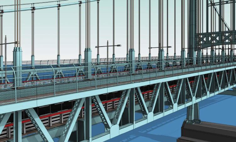
Figure 6. Combination retrofit.
Phase 2 Verification Testing
In this phase of the testing program, the selected combination scheme from Phase 1 was tested for the following conditions:
- Turbulence
- Wind attack angles of +/‐ 1 degree
- Snow and ice accumulation in protective fences
Turbulent flow tests offer a more realistic indication of a bridge’s response in strong winds since the natural wind tends to be turbulent. In these tests, the effect of turbulence shows a comparatively small benefit towards an improvement in flutter wind speed of between 3 and 4 mph (Figure 7).
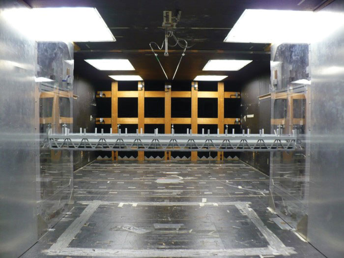
Figure 7. Section model test with turbulence. Courtesy of Boundary Layer Wind Tunnel Laboratory.
The angle of attack is the inclination of the wind to the horizontal plane of the deck, being positive when the windward leading edge moves upwards (“nose up”). Torsional flutter instability was observed for angles of attack of +1° and ‐1°; however, the wind speeds far exceed the flutter wind speed criterion of 105.4 mph (Figure 8).
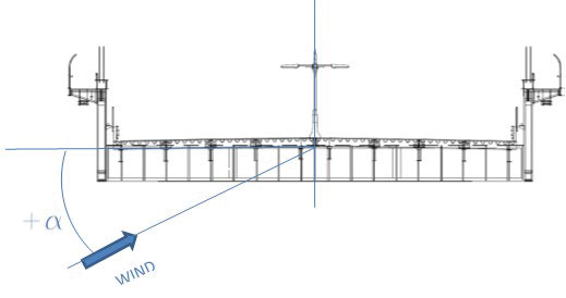
Figure 8. Attack angle on bridge section.
The effects of icing and snow accumulation were also explored in the Phase 2 sensitivity tests; the concern was that snow and icing would increase the solidity of fencing elements, thereby reducing the flutter wind speed. Various icing conditions were represented by different porosities and tape was used over fence and barrier components to simulate these conditions. The tests were conducted to provide insight into the sensitivities of bridge vibrations to icing conditions. Results showed that flutter wind speeds were reduced significantly when there is ice in fences on walkways and roadways. However, this condition should not be of major concern due to the low probability of the combination of extreme ice and wind conditions. Also, the Triborough Bridge and Tunnel Authority (TBTA) facility have the option of removing ice on fences if necessary.
Sidewalk Extension Study
The suspended span has two sidewalks located at the top of the stiffening trusses. Sidewalks are about 6 feet wide. One side is currently used for pedestrians, and the other side is used only for maintenance and inspection. Given the possibility that sidewalk modification may be part of future capital programs and the possibility that it may enhance future bridge aeroelastic behavior, additional studies of sidewalk extensions were performed with the recommended retrofits from the Phase 1 and 2 tests.
Critical wind speeds for flutter instability and wind effects based on geometry and dynamic properties of the following configurations of the bridge were studied:
- Two 10-foot wide new sidewalks – one situated on each side of the bridge
- One 12-foot wide new sidewalk on one side, with the other sidewalk at existing width (i.e. 6-foot wide)
For all tested sidewalk widening cases, all the flutter wind speeds in smooth flows meet the criterion of the 10,000‐year return period wind speed, as shown in Table 3. It was observed that increasing walkway width improves aerodynamic stability by increasing flutter wind speed.
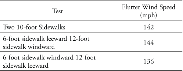
Table 3. Sidewalk extension study.
Wind on Vehicle Study
High wind conditions are the frequent cause of vehicle rollovers or skidding, often forcing the shutdown of major roadways and halting the movement of traffic.
Wind tunnel tests were conducted to determine the wind forces that act on an array of wind sensitive vehicles. The forces were used to evaluate the behavior of vehicles and susceptibility to overturning and skidding on the suspended spans with proposed wind retrofits developed in the previous phases. The results of the tests were used to assess the relative wind forces that users of the bridge may experience and to assess the relative differences in the forces which act on high‐sided vehicles. The tests were performed using force balance models of the following vehicles: a) a truck/semi‐trailer, b) a truck/double trailer, c) a highway bus and d) delivery van.
For testing vehicles on the bridge, the existing section model from previous wind tunnel testing was used, with the retrofits as included. The vehicle models were attached to the bridge deck in each of the four northbound traffic lanes and mounted on a rig on the turntable which allowed multiple wind angles to be examined (Figure 9). The instrumented vehicles were tested without traffic present in the remaining lanes to develop the critical loads for vehicle overturning. The measured forces on all vehicle types were integrated into an analytical vehicle overturning model which assessed the sensitivity to vehicle overturning and potential handling difficulty experienced by drivers in high winds.
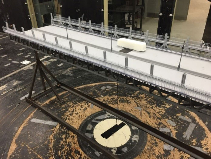
Figure 9. Wind on vehicle test. Courtesy of Boundary Layer Wind Tunnel Laboratory.
Test results showed that stiffening trusses and protective fences in the suspended spans had a shielding effect on vehicles and provided enhanced resistance to blow over. Compared to the results from the ground tests, there is an average 24 mph increase in critical wind speeds when the vehicles are placed in suspended spans (Figure 10).
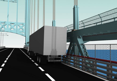
Figure 10. Shielding effects of bridge stiffening truss.
Conclusions
As a major long-span bridge in the New York City Metro area, the Robert F. Kennedy Bridge needed to be evaluated for strength, serviceability, and stability. Wind tunnel testing demonstrated that the suspended span did not meet the 10,000-year stability requirement of 105.4 mph. The innovative solution proposed was replacing solid roadway barriers with open barriers and replacing the deep fascia girder on the walkway with a shallower girder railing, increasing flutter wind speed to 130 mph including protective fences. An extensive wind on vehicle testing program was also performed. Lane by lane tests were conducted on wind sensitive vehicles for overturning and skidding for multiple wind azimuths. Test findings demonstrated that such vehicles are very safe, thanks to the shielding effects of the stiffening trusses.▪
Project Team
Owner: MTA Bridges and Tunnels – TBTA
Joint Venture: Thornton Tomasetti – Weidlinger Transportation, T.Y. Lin International
Wind Consultant: Boundary Layer Wind Tunnel Laboratory at the University of Western Ontario.